Connect Networks With Overlapping CIDRs
The Scenario
This document illustrates an example solution to a use case where a customer needs to:
-
Connect certain on-prem hosts to certain virtual machine (EC2/GCE) instances in a VPC/VNet over an IPsec tunnel over the Internet
-
Their on-prem network range overlaps with the VPC/VNet CIDR range
-
No NAT function will be performed on the customer side
-
Traffic can be initiated from either side
| This solution works for specific hosts and virtual machine instances on each side. |
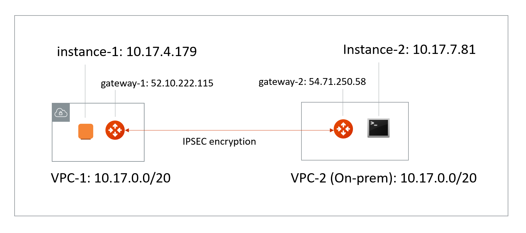
The scenario is described in the following diagram, where VPC/VNet-2 represents an on-prem environment.
-
VPC/VNet-1 CIDR = 10.17.0.0/20; instance-1 in VPC/VNet-1 has an IP address 10.17.4.179.
-
VPC/VNet-2 CIDR = 10.17.0.0/20; instance-2 in VPC/VNet-2 has an IP address 10.17.7.81.
The Solution
The solution is to build a Site2Cloud IPsec tunnel between VPC/VNet-1 and VPC/VNet-2 and apply both source NAT (SNAT) and destination NAT (DNAT) on VPC/VNet-1 gateway. The packet flow is demonstrated as below:
-
instance-1 sends a packet to instance-2 with a virtual destination IP address, for example 172.16.0.43. From instance-1’s point of view, the destination instance is a virtual address - 172.16.0.43.
-
When the packet arrives at the VPC/VNet-1 gateway, the gateway does DNAT on the packet to translate the virtual destination IP address to 10.17.7.81 which is the instance-2 physical IP address.
-
The gateway at VPC/VNet-1 then translates the packet source IP address (10.17.4.179) to a virtual source IP address (for example, 192.168.0.43).
-
The packet then arrives at VPC/VNet-2 with destination IP address 10.17.7.81 and source IP address 192.168.0.43. From instance-2’s point of view, instance-1’s address is a virtual IP address - 192.168.0.43.
-
When instance-2 sends a packet to instance-1, the destination is the virtual IP address 192.168.0.43.
-
When the packet arrives at the VPC/VNet-1 gateway over the IPsec tunnel, the VPC/VNet-1 gateway translates its destination IP address from virtual address 192.168.0.43 to 10.17.4.179.
-
The VPC/VNet-1 gateway then translates the source IP address of the packet from 10.17.7.81 to virtual address 172.16.0.43.
The Configuration Steps
Launch Gateways
Create a Spoke Gateway. Leave optional parameters unchecked.
Creating External Connections
-
Create a Static Route-Based (Mapped) external connection for VPC-1/Gateway-1 using the following information:
Field Value Name
S2C-VPC-OnPrem (for example)
Connect Public Cloud To
Static Route-Based (Mapped)
Local Gateway
Select the Aviatrix Gateway created earlier in this document
Real Local Subnet CIDR(s)
10.24.0.0/20 (VPC-Cloud Network CIDR; subnet of VPC-1)
Virtual Local Subnet CIDR(s)
Any/20 (VPC-Cloud Network Virtual CIDR)
Remote Device Type
Generic
Real Remote Subnet CIDR(s)
10.24.0.0/20 (On-Prem Network CIDR; subnet of the on-prem router)
Virtual Remote Subnet CIDR(s)
Any/20 (On-Prem Network Virtual CIDR)
Pre-Shared Key
Optional (auto-generated if not entered)
Remote Device IP
Public IP of IOS Router WAN port (52.40.45.197 in this example)
Local Gateway Instance
Select the Gateway instance to associate with this IP (especially important if you are adding a second instance for HA)
Leave optional parameters Off (Over Private Network/IKEv2/Algorithms). You can add a secondary Connection (instance) for HA if required.
|
The Local & Remote Subnet (virtual) IP range can be anything but the subnet should be the same as the Physical/Real subnet. |
-
Click Save.
-
Create an Unmapped external connection for VPC/VNet-2 Gateway-2 using one of these options:
Field Value Name
VPC-2-to-VPC-1 (for example)
Connect Public Cloud To
Static Route-Based (Unmapped) or Static Policy-Based (Unmapped)
Local Gateway
Select the Aviatrix Gateway created earlier in this document
Local Subnet CIDR(s)
10.17.7.81/32
Remote Device Type
Generic
Remote Subnet CIDR(s)
192.168.0.43/32
Pre-Shared Key
Optional (auto-generated if not entered)
Remote Device IP
52.10.222.115
Local Gateway Instance
Select the Gateway instance to associate with this IP (especially important if you are adding a second instance for HA)
-
Click Save.
-
Go to Diagnostics > Cloud Routes > External Connections tab to check the tunnel status.
|
You do not need to download the configuration because both ends of the network are on the VPC/VNet. Make sure the pre-shared Keys are the same for both ends. In the above example, "Aviatrix101#" can be used as the pre-shared key. |
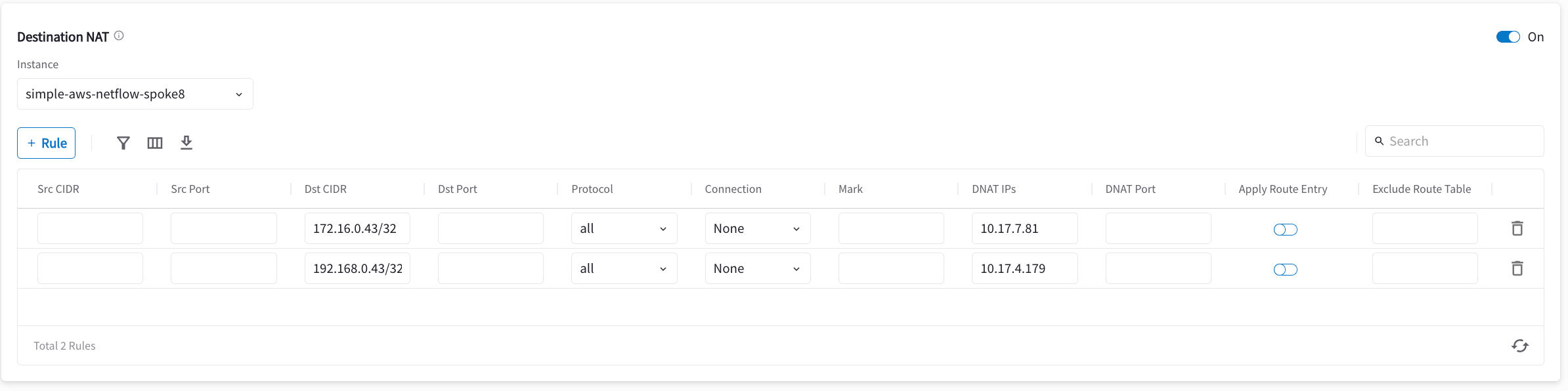
Configuring DNAT on Gateway-1
You now configure the gateway to translate the destination IP address 172.16.0.43 to the real private IP address 10.17.7.81, before routing happens.
-
Go to Cloud Fabric > Gateways > Spoke Gateways.
-
Click the name of the gateway you created earlier in this document.
-
Click the Settings tab and expand the Network Address Translation (NAT) area.
-
Turn On Destination NAT.
-
Add rules as per the screenshot below.
-
Turn On Apply Route Entry for each rule to commit the rule(s).
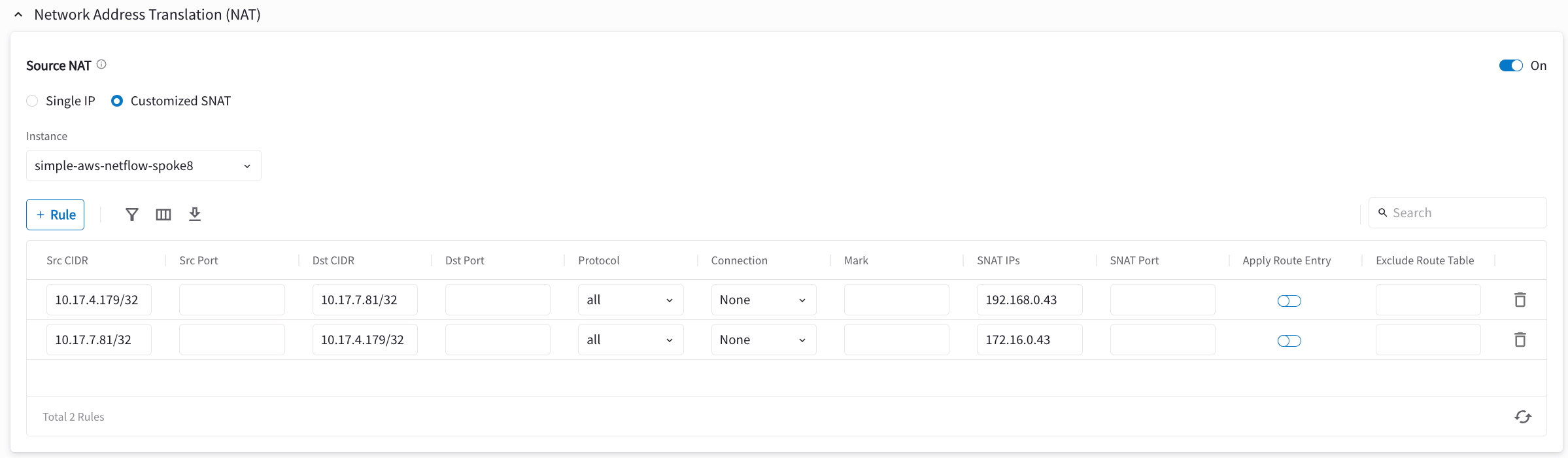
Configuring SNAT on Gateway-1
This step is to translate the packet source IP address after routing happens. In this example, the address is translated from 10.17.7.81 to 172.16.0.43 for packets going from on-prem (VPC/VNet-2) to VPC/VNet-1, and 10.17.4.179 to 192.168.4.43 for packets going from VPC/VNet-1 to on-prem (VPC/VNet-2).
On the same VPC/VNet-1 gateway, configure SNAT as shown below (turn On Source NAT and then click Customized SNAT).
You can enter "Dst CIDR" as qualifier to reduce the scope of the rule as a good practice. The reason that the address is 10.17.7.81/32 is that the destination has already been translated after the DNAT rule before routing happens.