Networks with Overlapping CIDRs Scenarios
This document describes a few scenarios of overlapping networking CIDRs and their solutions. The solution uses the Mapped option of the Aviatrix Site2Cloud feature when building IPsec tunnels.
Using Mapped Site2Cloud provides the advantage of not having to configure individual SNAT/DNAT rules, as all virtual and physical network addresses are 1-1 translated.
This document does not go into specifics of the actual configurations. For this information, see Configuring Overlapping Networks with Network Mapped IPsec.
Scenario 1: On-prem Overlaps with Spoke in Aviatrix Transit Deployment
In this scenario, the Aviatrix Transit solution is deployed, and a resource on the on-prem site overlaps with a Spoke CIDR it needs to communicate with, as shown in the diagram below.
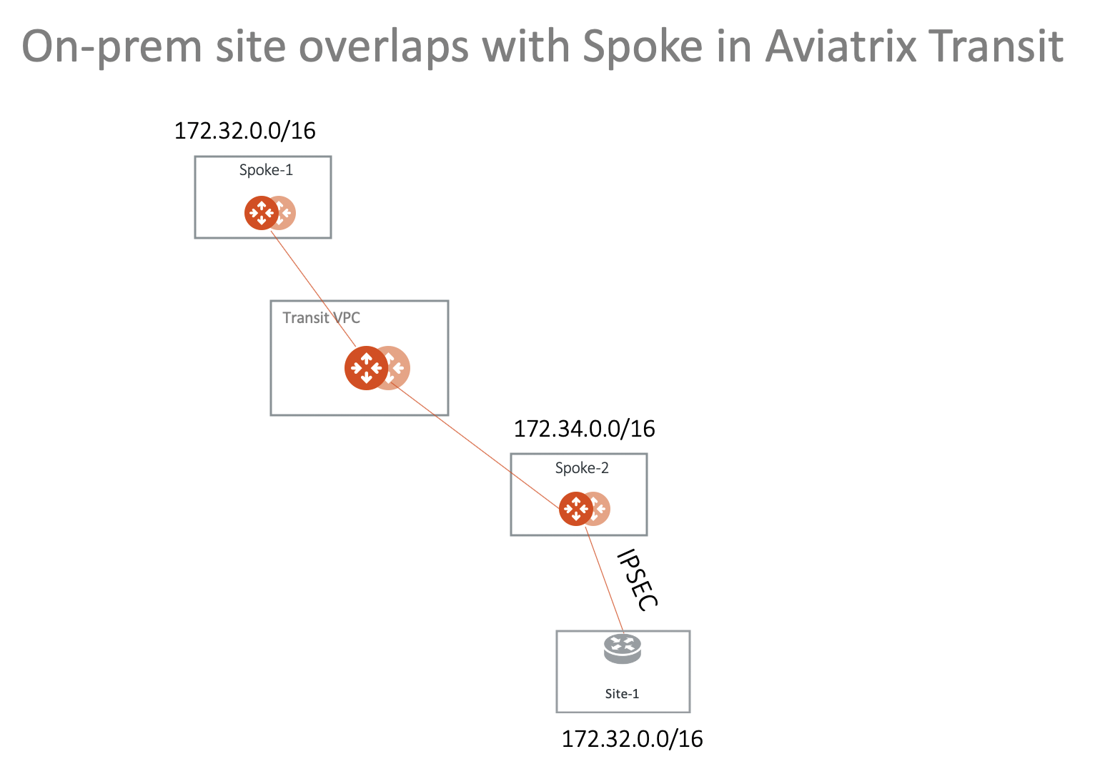
This scenario is made possible by the Forward Traffic to Transit Gateway option that you can enable after configuring your Site2Cloud connection. See Forwarding Traffic to Transit Gateway for more information.
Scenario 2: Multi-Sites Overlap in Aviatrix Transit Deployment
This scenario extends the previous solution to include multi-sites, as shown in the diagram below.
This scenario is made possible by the Forward Traffic to Transit Gateway option that you can enable after configuring your Site2Cloud connection. See Forwarding Traffic to Transit Gateway for more information.
Spoke 2 in this scenario is a landing Spoke. When the Site2Cloud Forwarding option referenced above is enabled, NAT occurs on the landing Spoke and ensures that bidirectional traffic flow is possible between on-prem routers and local Spoke and Transit gateways.
Either side can now initiate traffic (locally or remotely), as per what you configured in your Site2Cloud connection. If you select only one of these, you cannot initiate from the other direction and NAT translation will not occur.
Enabling the Auto Advertise Spoke Site2Cloud CIDRs option (select a Spoke Gateway and select this option from the Settings tab) in this scenario ensures that the other Spokes in the scenario are aware of the virtual CIDRs on which the landing Spoke is going to perform NAT (Spoke 2).
If you select this Auto Advertise option ensure that you do not advertise more than the CSP-allowed limit of routes per route table. For example, for AWS the routes per route table limit is described here.
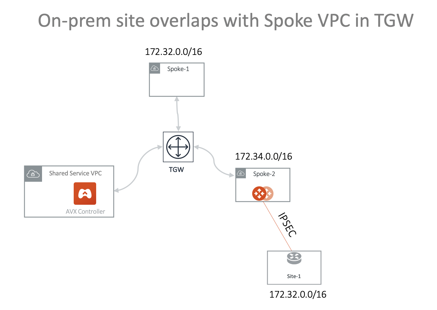
Scenario 3: On-prem Overlaps with Spoke VPC/VNet in TGW Deployment
In this scenario, on-prem site-1 overlaps with Spoke-1 VPC/VNet CIDR. They are both 172.32.0.0/16 and want to communicate with each other. The solution is to deploy an Aviatrix Gateway in Spoke-2 VPC/VNet and build an IPsec tunnel between Spoke-2 gateway and the on-prem. In the deployment, both Spoke-1 and Spoke-2 are attached to TGW and are in the same Network Domain.
The diagram shown below illustrates how to use Spoke VPC Advertised Routes to build a more complex network. You can launch an Aviatrix Gateway in Spoke-1 directly and build the IPsec tunnel.
| VPC Spoke-1 is for illustration purposes. The destination network that overlaps with the on-prem site may be an on-prem network that connects with AWS TGW via AWS Direct Connect or VPN. Similarly, the on-prem network could be a VPC/VNet in the cloud. |
Following are the steps to set up the above networks.
-
Launch Aviatrix gateway in Spoke-2. You can add an instance when creating the Spoke Gateway if you want to use HA.
-
Create a Static Route-Based (Mapped) connection from Spoke-2 to Site-1 using these values:
-
Local Subnet (real): 172.32.0.0/16
-
Local Subnet (virtual): 192.168.0.0/16
-
Remote Subnet (real): 172.32.0.0/16
-
Remote Subnet (virtual): 100.100.0.0/16
-
-
Configure the on-premises site-1 IPsec. Key parameters are:
-
Local Subnet: 172.32.0.0/16
-
Remote Subnet: 192.168.0.0/16
You can download the configuration from step 4 to use in the on-prem configuration.
-
-
Check the tunnel status at Diagnostics > Cloud Routes > External Connections.
|
Advertise 100.100.0.0/16 to TGW from Spoke-2 VPC/VNet:
|
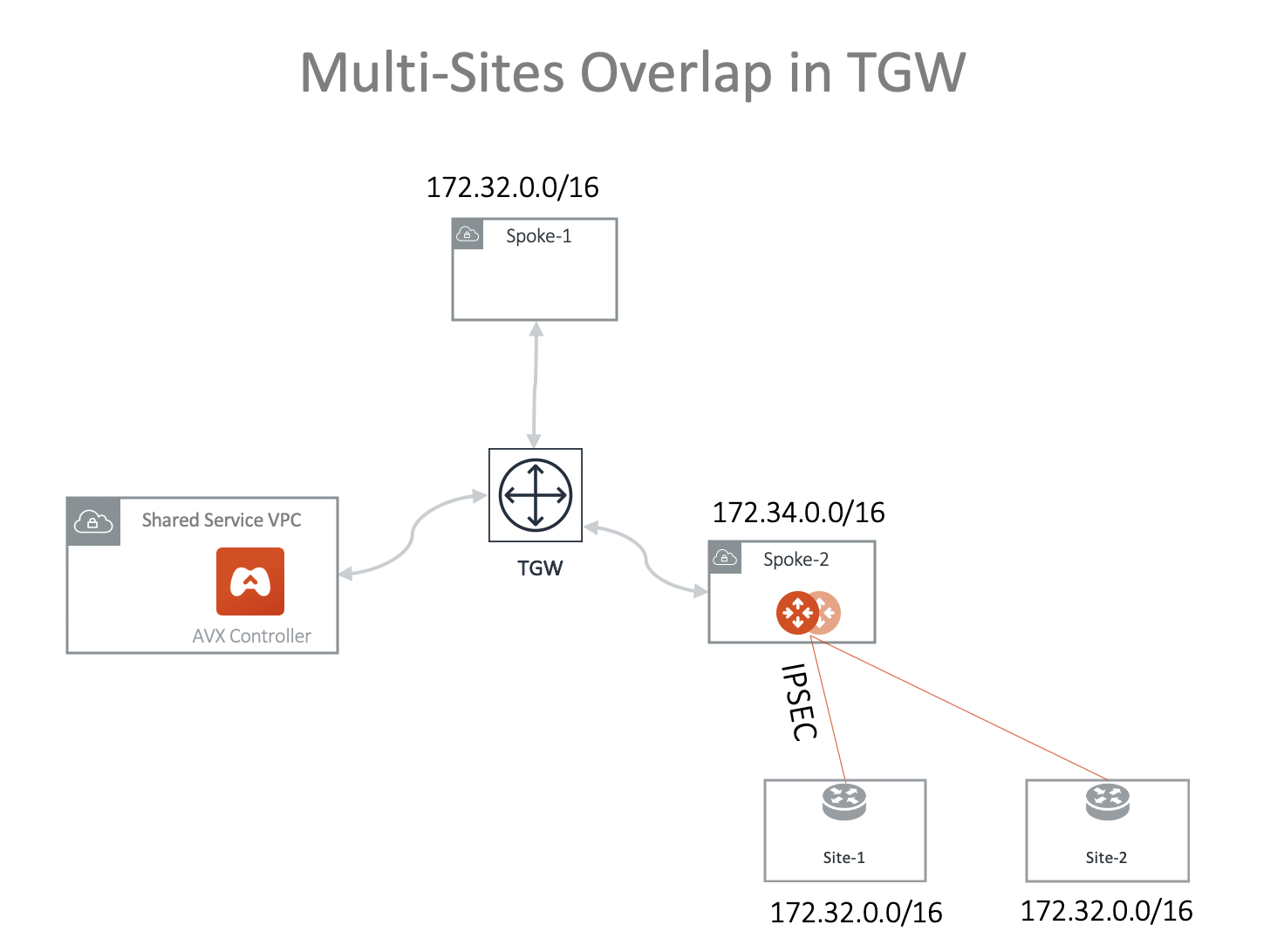
Scenario 4: Multi-Sites Overlap in TGW Deployment
Scenario 1 can be extended to on-prem multi sites that have overlapping or identical network addresses, as shown in the diagram below.
-
Launch Aviatrix gateway in Spoke-2. You can add an instance when creating the Spoke Gateway if you want to use HA.
-
Create a Static Route-Based (Mapped) connection from Spoke2 to Site-1 using these values:
-
Local Subnet (real): 172.32.0.0/16
-
Local Subnet (virtual): 192.168.0.0/16
-
Remote Subnet (real): 172.32.0.0/16
-
Remote Subnet (virtual): 100.100.0.0/16
-
-
Create an on-premises site-1 to Spoke-2 Gateway IPsec connection with an on-premises router or firewall:
-
Route Based VPN
-
Local Subnet: 172.32.0.0/16
-
Remote Subnet: 192.168.0.0/16
-
-
Check the tunnel status at Diagnostics > Cloud Routes > External Connections.
-
Create a Static Route-Based (Mapped) connection from Spoke-2 to Site-2 using these values:
-
Local Subnet (real): 172.32.0.0/16
-
Local Subnet (virtual): 192.168.0.0/16
-
Remote Subnet (real): 172.32.0.0/16
-
Remote Subnet (virtual): 100.200.0.0/16
-
-
Create an on-prem site-2 to Spoke-2 gateway IPsec connection with an on-prem router or firewall. Key parameters:
-
Route Based VPN
-
Local Subnet: 172.32.0.0/16
-
Remote Subnet: 192.168.0.0/16
-
|
Advertise 100.100.0.0/16 100.200.0.0/16 to TGW from Spoke-2 VPC/VNet:
|
Solving Overlapping IP Addresses
Real-world use cases sometimes require a combination of Site2Cloud and other features, such as SNAT and DNAT.
To learn more, see Configuring Overlapping Networks with Customized SNAT and DNAT.