Solving Overlapping Networks with Network Mapped IPsec
The Scenario
This tech note illustrates an example solution to a specific use case. In this AWS use case, a customer needs to connect certain on-prem hosts to certain EC2 instances in a VPC over an IPsec tunnel over the Internet, but the on-prem network range overlaps with the VPC CIDR range, and the requirement from the customer is that no NAT function will be performed on the customer side. In addition, traffic can be initiated from either side.
The scenario is described in the following diagram:
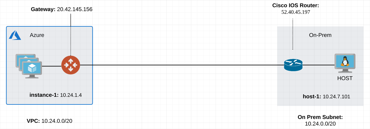
VPC       CIDR = 10.20.0.0/20, instance-1 in VPC-1 has an IP address 10.24.1.4.
On-Prem   CIDR = 10.20.0.0/20, host-1 in On-Prem has an IP address 10.24.7.101.
The traditional solution is to build IPsec tunnel between the two networks and use SNAT/DNAT rules to translate each addresses, as demonstrated in this example. Such solution requires a potentially large number of SNAT/DNAT rules which is difficult to configure and maintain.
The Solution
The new solutions uses a new "network mapped" feature in Site2Cloud that removes the need to configure individual SNAT/DNAT rules.
This solution uses a Site2Cloud route-based IPsec tunnel using Virtual Tunnel Interface (VTI) between VPC and On-Prem Router. The packet flow is demonstrated as below:
-
instance-1 sends a packet to host-1 with a virtual destination IP address, for example 192.24.7.101. From instance-1’s point of view, the destination instance is a virtual address - 192.24.7.101.
-
When the packet arrives at the VPC-1 gateway, the gateway does DNAT on the packet to translate the virtual destination IP address to 10.24.7.101 which is the host-1 physical IP address.
-
The gateway at VPC then translates the packet source IP address (10.24.1.4) to a virtual source IP address, say it is 172.24.1.4.
-
The packet then arrives at On-Prem Cisco IOS Router with destination IP address 10.24.7.101 and source IP address 172.24.1.4. From host-1’s point of view, instance-1’s address is a virtual IP address - 172.24.1.4.
-
When host-1 sends a packet to instance-1, the destination is the virtual IP address 172.24.1.4.
-
When the packet arrives at the VPC-1 gateway over the IPSEC tunnel, the VPC gateway translates its destination IP address from virtual address 172.24.1.4 to 10.24.1.4.
-
The VPC gateway then translates the source IP address of the packet from 10.24.7.101 to virtual address 192.24.7.101.
The Configuration Steps
Following the Site2Cloud Workflow to Launch Gateways
Log in to your Aviatrix Controller and select Site2Cloud on the left sidebar. Follow step 1 to launch a gateway in the VPC/VNet-1.
(You can follow the gateway launch instructions in this. Leave optional parameters unchecked.)
For the above example, we also launch a gateway in VPC/VNet-2 to emulate an on-prem environment.
Creating a Site2Cloud Tunnel
Go to Controller > Site2Cloud.
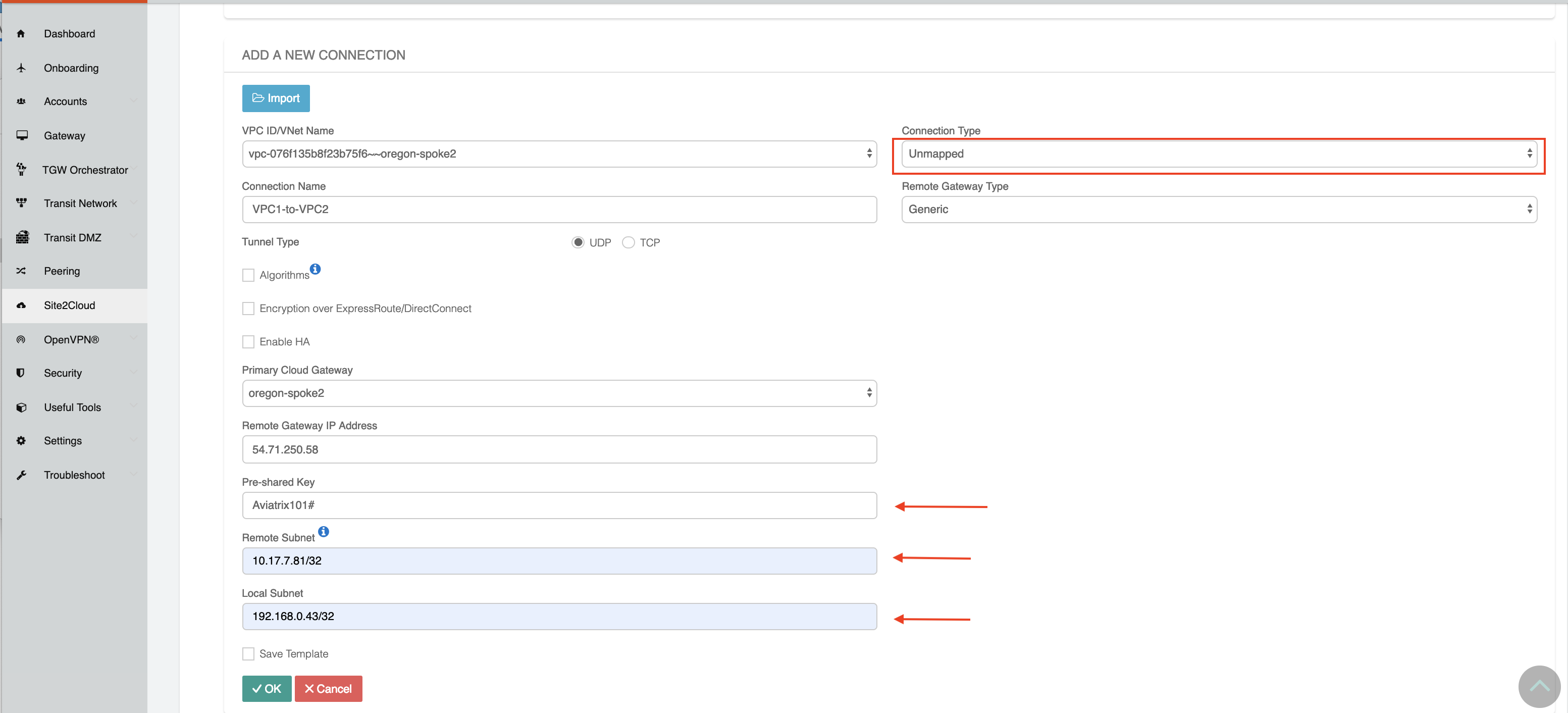
Click +Add New. Fill the form and click OK. Select Unmapped for the Connection Type field.
VPC/VNet-1 gateway-1 side
For the VPC/VNet-1 gateway side, the Local Subnet field should be 192.168.0.43/32, and the Remote Subnet field should be 10.17.7.81/32, as shown below.
Configure On-Prem Cisco Router
-
Go to the Site2Cloud page. From the Site2Cloud connection table, select the connection created above (e.g. S2C-VPC-OnPrem) and click
- "Edit".
-
From the Vendor drop down list select Cisco.
-
From the Platform drop down list select ISR, ASR, or CSR.
-
From the Software drop down list select IOS(XE).
-
Click the Download Configuration button to download the Cisco IOS Site2Cloud configuration.
-
Save the configuration file as a reference for configuring your Cisco IOS router.
The following is a sample configuration based on the Site2Cloud configuration above.
Either ssh into the Cisco router or connect to it directly through its console port.
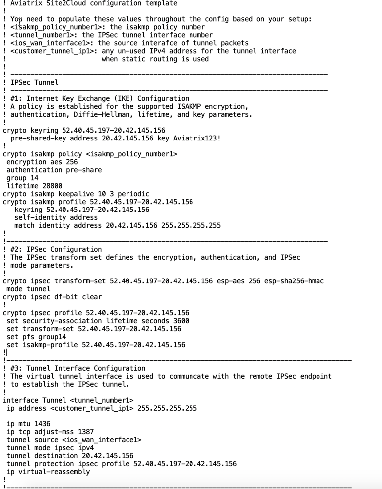
Apply the following IOS configuration to your router:
! Aviatrix Site2Cloud configuration template
!
! You need to populate these values throughout the config based on your setup:
! <isakmp_policy_number1>: the isakmp policy number
! <tunnel_number1>: the IPsec tunnel interface number
! <ios_wan_interface1>: the source interface of tunnel packets
! <customer_tunnel_ip1>: any un-used IPv4 address for the tunnel interface
!                        when static routing is used
!
! --------------------------------------------------------------------------------
! IPsec Tunnel
! --------------------------------------------------------------------------------
! #1: Internet Key Exchange (IKE) Configuration
! A policy is established for the supported ISAKMP encryption,
! authentication, Diffie-Hellman, lifetime, and key parameters.
!
crypto keyring 52.40.45.197-20.42.145.156
  pre-shared-key address 20.42.145.156 key <key>
!
crypto isakmp policy 1
 encryption aes 256
 hash sha256
 authentication pre-share
 group 14
 lifetime 28800
crypto isakmp keepalive 10 3 periodic
crypto isakmp profile 52.40.45.197-20.42.145.156
   keyring 52.40.45.197-20.42.145.156
   self-identity address
   match identity address 20.42.145.156 255.255.255.255
!
!---------------------------------------------------------------------------------
! #2: IPsec Configuration
! The IPsec transform set defines the encryption, authentication, and IPsec
! mode parameters.
!
crypto ipsec transform-set 52.40.45.197-20.42.145.156 esp-aes 256 esp-sha256-hmac
 mode tunnel
crypto ipsec df-bit clear
!
crypto ipsec profile 52.40.45.197-20.42.145.156
 set security-association lifetime seconds 3600
 set transform-set 52.40.45.197-20.42.145.156
 set pfs group14
 set isakmp-profile 52.40.45.197-20.42.145.156
!
!---------------------------------------------------------------------------------------
! #3: Tunnel Interface Configuration
! The virtual tunnel interface is used to communicate with the remote IPsec endpoint
! to establish the IPsec tunnel.
!
interface Tunnel1
 ip address 10.10.10.10 255.255.255.255
 ip mtu 1436
 ip tcp adjust-mss 1387
 tunnel source GigabitEthernet1
 tunnel mode ipsec ipv4
 tunnel destination 20.42.145.156
 tunnel protection ipsec profile 52.40.45.197-20.42.145.156
 ip virtual-reassembly
!
!---------------------------------------------------------------------------------------
! #4: Static Routing Configuration
! The static route directs the traffic to the Aviatrix remote subnets via the tunnel
! interface.
!
ip route 172.24.0.0 255.255.240.0 Tunnel1
!---------------------------------------------------------------------------------------
Wait for the tunnel to come up.