You must first have launched a firewall instance in the cloud portal.
- Example Configuration for Palo Alto VM-Series in AWS
- Example Configuration for Palo Alto Network VM-Series in GCP
- Example Configuration for Palo Alto Network VM-Series in OCI
| Palo Alto VM Interfaces | Description | Inbound Security Group Rule |
|---|---|---|
| eth0 (on subnet -Public-gateway-and-firewall-mgmt) | Management interface | Allow SSH, HTTPS, ICMP, TCP 3978 |
| eth1 (on subnet -Public-FW-ingress-egress) | Egress or Untrusted interface | Allow ALL |
| eth2 (on subnet -dmz-firewall_lan) | LAN or Trusted interface | Allow ALL (do not change) |
Logging into the VM-Series
Click the Management UI link on the FireNet tab to access the UI of the Palo Alto VM-Series firewall.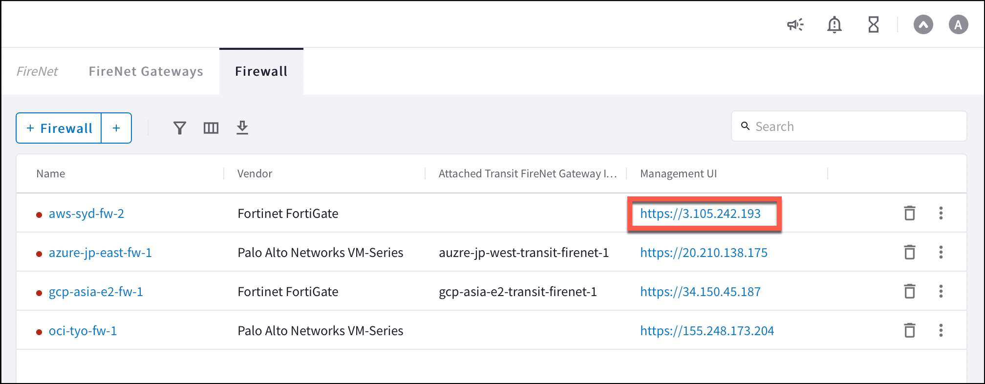
Dynamic Updates (all clouds)
To make sure your firewall is up to date, in your firewall UI you can navigate to Device > Dynamic Updates and click Check Now. You can then download and install the latest versions of Applications and Threat Wildfire updates.Configuring VM-Series Ethernet 1/1 with WAN Zone
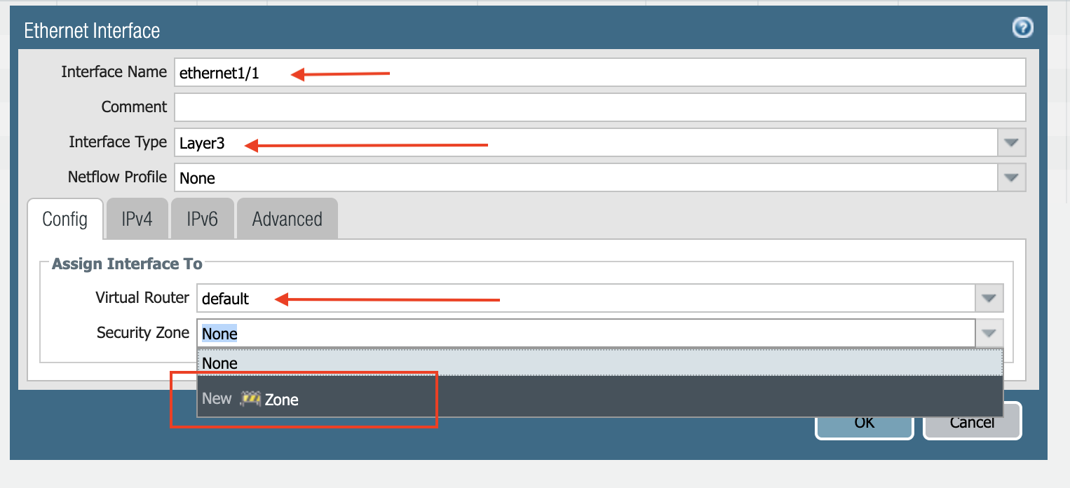
WAN is Wide Area Network. Ethernet 1/1 is Management Interface. Provides access to data center applications.- Once logged in, click on the Network tab to see a list of ethernet interfaces. Click ethernet1/1 and configure as per the following screenshot.
- Select the Network tab.
- Click ethernet1/1.
- Select layer3 for Interface Type.
- Select the Config tab in the popup Ethernet Interface window.
- Select default for Virtual Router at the Config tab.
- Click New Zone for Security Zone to create a WAN zone.
- At the next popup screen, name the new zone WAN and click OK.
- Select the IPV4 tab in the popup Ethernet Interface window.
- Select DHCP Client.
- Clear the Automatically create default route pointing to default gateway provided by server checkbox as shown below.
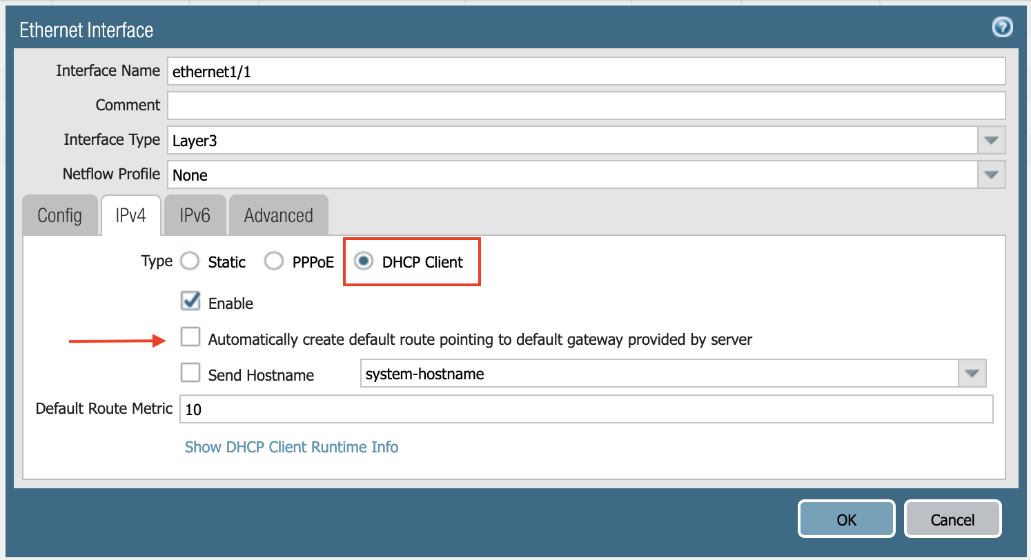
- Click Commit. Once Commit is complete, you should see the Link State turn green at the Network page for ethernet1/1.
Configuring VM-Series Ethernet 1/2 with LAN Zone
- Repeat the steps from Configuring VM-Series ethernet1/1 with WAN Zone section above for ethernet1/2. Name the new zone LAN.
- Click Commit. Once Commit is complete, you should see the Link State turn green at the Network page for ethernet1/2.
If Keepalive via Firewall LAN Interface is enabled for the FireNet where this firewall is deployed, ensure that ping is allowed in the Firewall LAN interface configuration: FireNet keep alive.
Vendor Firewall Integration
Use vendor integration to program RFC 1918 and non-RFC 1918 routes into the firewall.IPv6 vendor integration in Azure is currently not functional. If you require vendor-driven IPv6 route programming in Azure, configure IPv6 routes manually in the firewall.
Enabling VM-Series Health Check
Allowing access to HTTPS or TCP 443 port. not in the AWS procedure for Palo Alto setup.- Go to Network > Interface Mgmt under Network Profiles and click Add.
- Enter a name in the Interface Management Profile, mark the HTTPS checkbox under Administrative Management Service, and click OK.
- Attach Profile with LAN interface: Network > Interfaces > Select LAN Ethernet Interface > Advanced > Management Profile > Select appropriate profile.
Basic Traffic Policy to Allow Traffic VNet to VNet
In this step, we will configure a basic traffic security policy that allows traffic to pass through the VM-Series firewall.- Select the Policies tab.
- Click +Add in the bottom left corner to create a new policy.
- Select the General tab. Name the policy “Allow-all.”
- Select the Source tab. Select Any for both panels.
- Select the Destination tab. Select Any for both panels.
- Select the Application tab. Select Any.
- Click OK.
- Click Commit to commit the Allow-all policy.
Configuring Basic Traffic Policy to Allow Traffic VNet to Internet
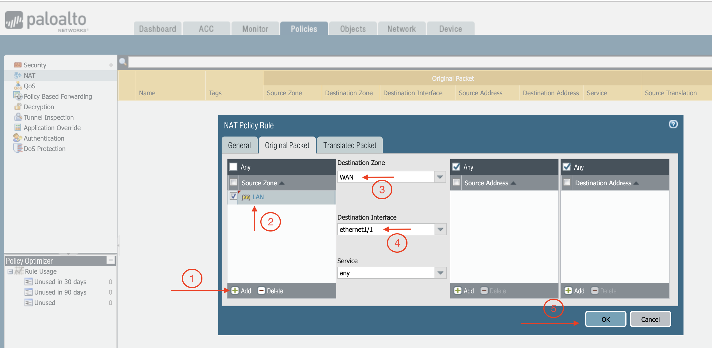
If you would also like to enable NAT to test egress, follow these steps.- Policies > NAT > click Add.
- Select the General tab, give it a name > click Original Packet.
- At Source Zone, click Add, and select LAN.
- At Destination Zone, select WAN. At Destination Interface, select Ethernet1/1, as shown below.
- Click Translated Packet. At Translation Type, select Dynamic IP And Port.
- At Address Type, select Interface Address.
- At Interface, select ethernet1/1, as shown below.