

Prerequisites
Before you enable VRF end-to-end propagation, confirm the following.- Controller version: Aviatrix Controller is running version 10.1 or later.
- Gateway software version: Both gateways in each peering you plan to configure (the spoke or Edge Spoke gateway and its peer Transit Gateway, or the two Transit Gateways in a transit-transit peering) must be running gateway software 10.1 or later.
- Existing first-hop VRF configuration: A first-hop VRF configuration from Controller 9.0 must already be in place: VRF support enabled at the controller level, with spoke gateways attached to their segmentation domains.
- Supported cloud service providers: AWS, Azure, and GCP are supported.
On Azure, VRF end-to-end propagation does not support spoke VPCs or VNets that have overlapping CIDR ranges.
- Existing spoke-transit or transit-transit peering: At least one peering already established between the gateways you want to propagate VRF end-to-end across.
- Administrative access: Access to Networking > Network Segmentation > Settings in CoPilot.
Enable VRF End-to-End Propagation
1
Open Network Segmentation settings
In Aviatrix CoPilot, go to Networking > Network Segmentation >
Settings.
2
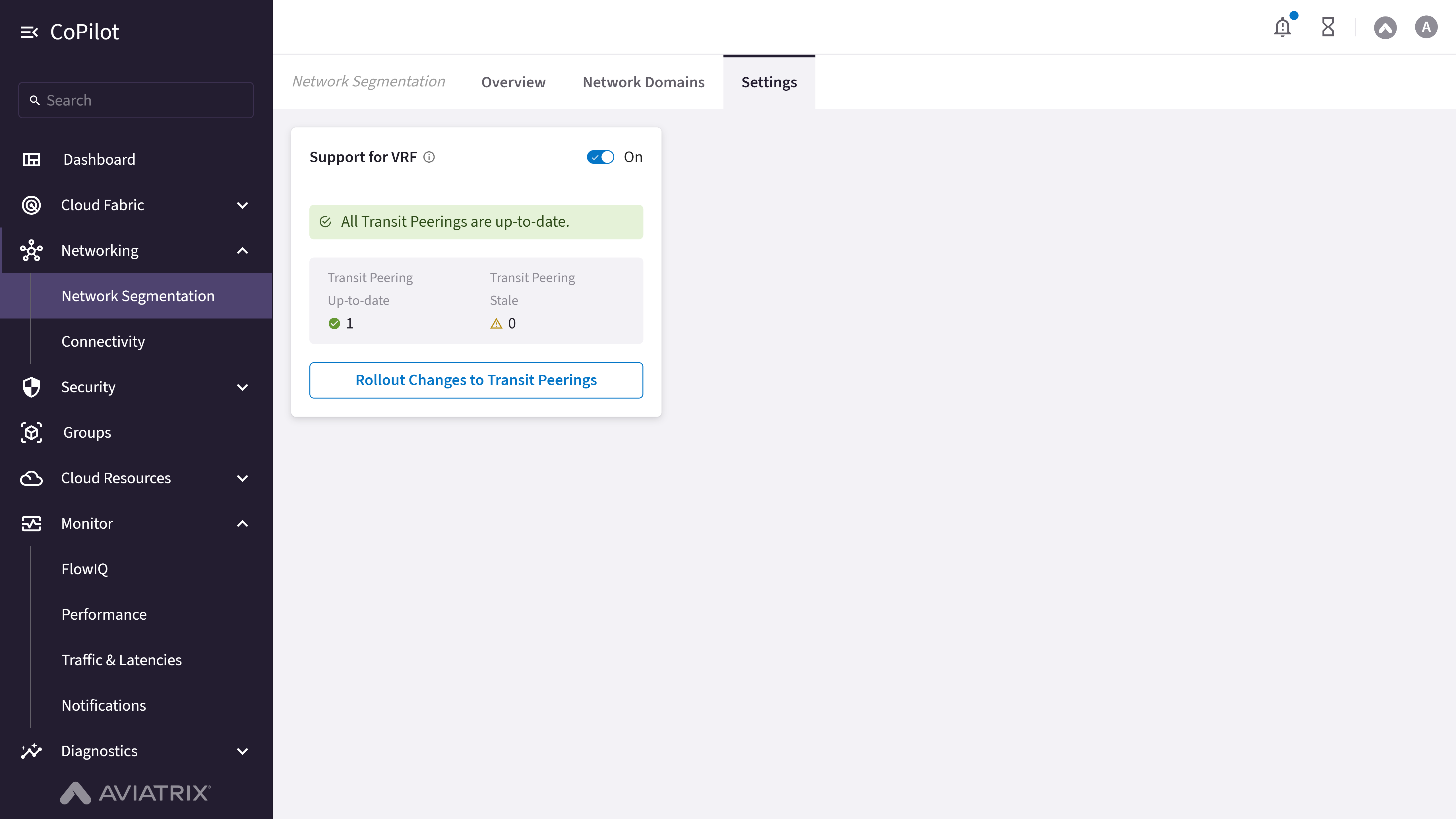
Confirm Support for VRF is enabled
Locate the Support for VRF card and confirm the toggle switch is set
to On. This reflects the first-hop VRF configuration from the
Prerequisites. If the toggle is Off, VRF has not
been enabled at the controller level, and you must complete
that configuration
before continuing.
3
Review peering attachment status
In the Support for VRF card, review the Transit Peering
Up-to-date and Transit Peering Stale counts. A peering counted as
stale has not yet had VRF end-to-end propagation applied.
4
Open the rollout dialog
Click Rollout Changes to Transit Peerings. The Rollout Support for
VRF dialog opens, listing every eligible peering with its Transit/Edge
Spoke Gateway, Peering Type (Intra-Group, Transit-Transit, Edge
Spoke-Transit, or BGP Spoke-Transit), and Transit Gateway Instance.
5
Select the peerings to propagate
Select the checkbox next to each spoke-transit (Edge Spoke-Transit or BGP
Spoke-Transit) or transit-transit peering where you want to enable VRF
end-to-end propagation. Clear the checkbox for any peering where you want
to disable it.
6
Roll out the change
Click Rollout. CoPilot applies the change to every selected peering.
Disabling Support for VRF entirely (turning the card’s main toggle
Off) affects every peering at once and causes all transit peerings to
become stale. Do not turn off the main toggle unless you intend to remove VRF
end-to-end propagation across your entire environment.
Verify Segment Identity in CoPilot
After you roll out the change, confirm that segment identity is propagating end-to-end across the peerings you selected.1
Recheck the peering attachment status
Return to Networking > Network Segmentation > Settings and
open the Support for VRF card. Confirm that the peerings you enabled
now count toward Transit Peering Up-to-date rather than Transit
Peering Stale.
2
Confirm the segmentation domain mapping
Confirm that each spoke’s segmentation domain (its VRF identity) is still
correctly reflected on Networking > Network Segmentation >
Network Domains after propagation.
Validate Traffic Isolation
VRF end-to-end propagation is only correctly configured if traffic within a segment still reaches its intended destinations and traffic across different segments remains blocked.1
Confirm same-segment connectivity
From a workload in one spoke, confirm connectivity to a workload in
another spoke that shares the same VRF segment across the peering you
configured. Connectivity should succeed.
2
Confirm cross-segment isolation
From the same workload, attempt connectivity to a workload in a spoke
that belongs to a different VRF segment across the same peering. The
connection should fail, confirming that traffic isolation between
segments is preserved end-to-end.
3
Inspect VRF-tagged tunnel traffic (optional)
To inspect the underlying tunnel traffic instead of only its
connectivity outcome, go to Diagnostics > Diagnostic Tools >
Gateway Diagnostics > Packet Capture and select the gateway
whose tunnel you want to inspect. If both the Controller and the
selected gateway are on 10.1 or later, a Skip Aviatrix Headers
toggle appears; enabling it strips the Aviatrix VRF tunnel headers from
the capture so filters and saved captures show the original inner
packets instead of the VRF-tagged outer headers.