

This is not a common scenario. You would only set up this type of connection
if you want to connect an Aviatrix Transit gateway to a firewall that is
outside your Cloud service provider (for example, in a branch office or
warehouse).
- VPC1 (with Aviatrix Transit Gateway)
- VPC1 CIDR: 10.5.0.0/16
- VPC1 Public Subnet CIDR: 10.5.3.0/24
- VPC1 Private Subnet CIDR: 10.5.2.0/24
- VPC2 (with Palo Alto Networks VM-series)
- VPC2 CIDR: 10.0.0.0/16
- VPC2 Public Subnet CIDR: 10.0.0.0/24
- VPC2 Private Subnet CIDR: 10.0.1.0/24
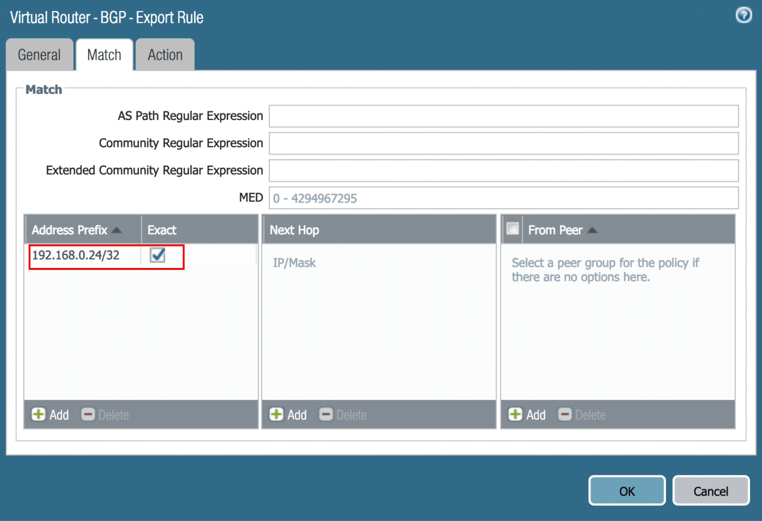
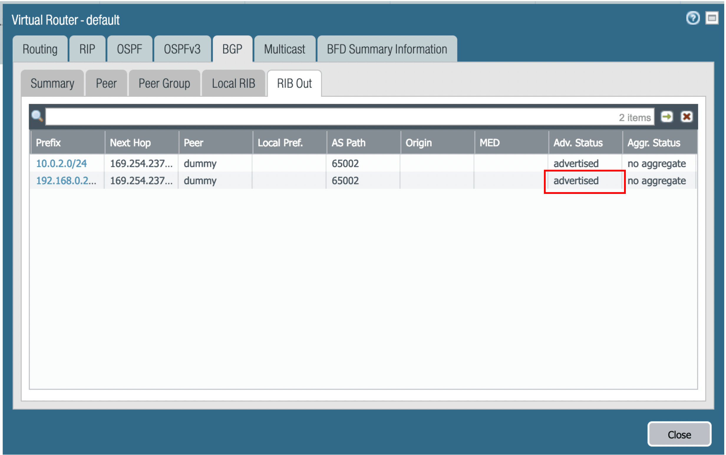
- Sample subnet advertised with the help of BGP - 192.168.0.24/32 (loopback interface on PaloAlto)
- In CoPilot, navigate to Cloud Fabric > Gateways > Transit Gateways.
- Create a Transit gateway in AWS that will connect to your Palo Alto firewall.
- To connect the transit VPC GW to Palo Alto, navigate to Networking > Connectivity > External Connections.
- Click +External Connection.
-
In the Add External Connection dialog, configure the following:
- Click Save.
- Download the configuration .
-
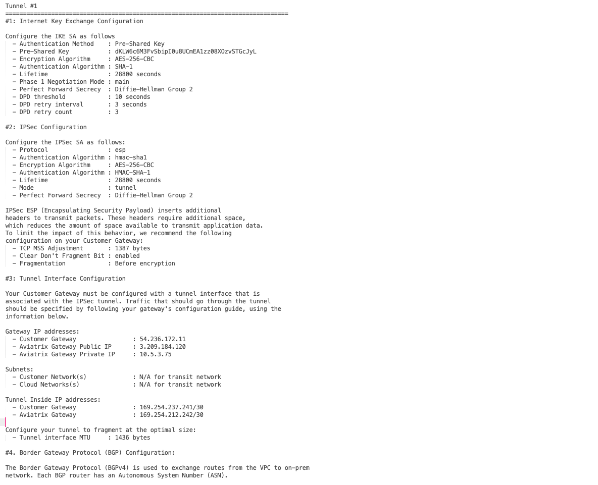
Use the information in the downloaded file to configure the router.
The following is a sample configuration based on the Site2Cloud configuration
above.
Configuring the Palo Alto VM-Series Firewall
Log into Palo Alto Networks VM Series and configure it as follows:-
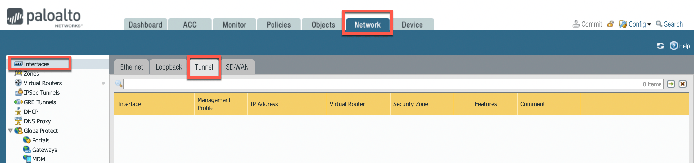
Navigate to Network > Interfaces > Tunnel.
-
Click Add to create a new tunnel interface. In the Tunnel Interface dialog,
on the Config tab, assign the following parameters.
 Click the IPv4 tab and add the tunnel IP address from the configuration downloaded above.If the tunnel interface is in a zone different from the one where the traffic will originate, you must create a policy to allow the traffic to flow from the source zone to the zone containing the tunnel interface.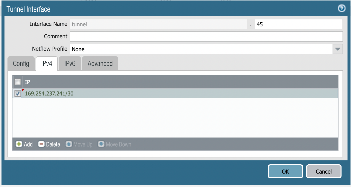
- Click OK.
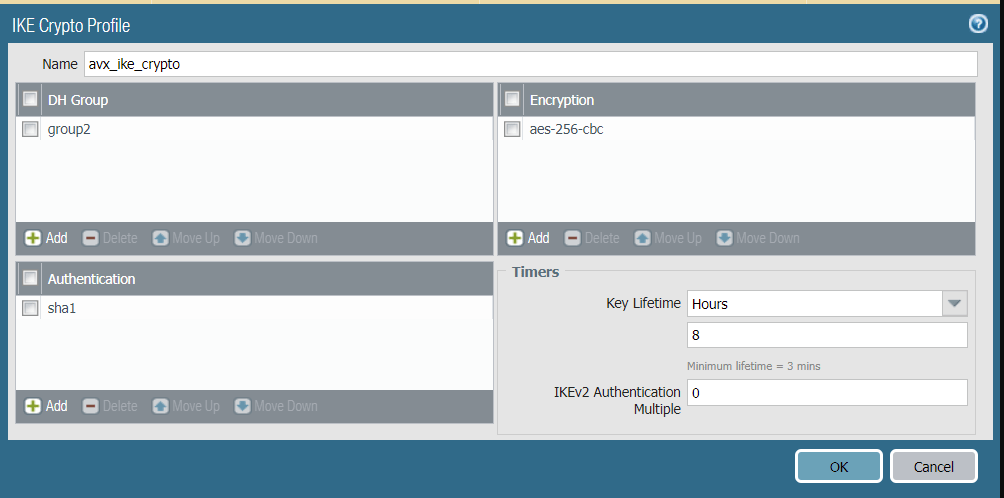
- Navigate to Network > Network Profiles > IKE Crypto.
- Click Add.
-
In the IKE Crypto Profile dialog, define the IKE Crypto profile (IKEv1
Phase-1) parameters as shown.
- Click OK.
- Navigate to Network > Network Profiles > IKE Gateways and click Add.
-
In the IKE Gateway dialog, configure the IKE Phase-1 Gateway as shown below.
These parameters should match the Site2Cloud configuration
downloaded here.
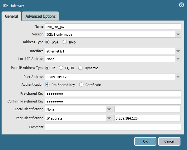
- On the Advanced Options tab, select the IKE Crypto Profile created in step 6.
- Click OK.
- Navigate to Network > Network Profiles > IPSec Crypto.
- Click Add to create a new profile.
-
In the IPSec Crypto Profile dialog, define the IPSec crypto profile (IKEv1
Phase-2). These parameters should match the relevant values in the downloaded
configuration.
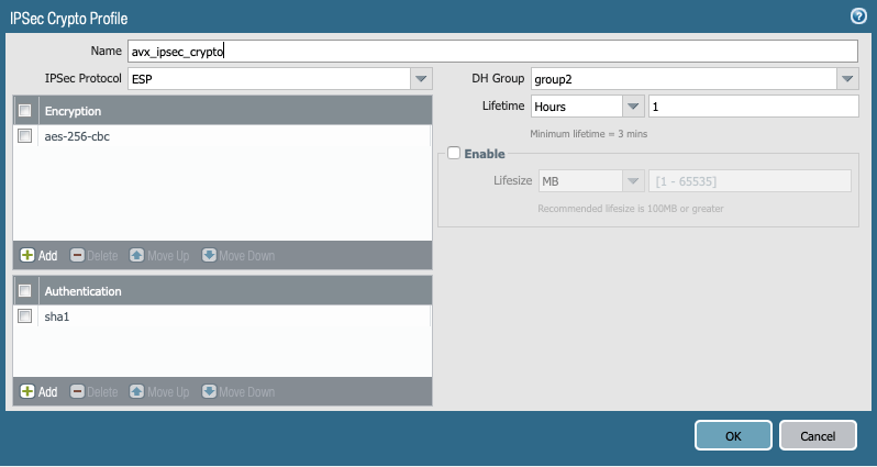
- Click OK.
- Navigate to Network > IPSec Tunnels and click Add to create a new IPSec Tunnel.
-
Configure the General tab as follows:
 There is no need to configure proxy-id. Commit the configuration. The IPSec tunnel should now be green.
-
Steps to configure BGP: a. Navigate to Network > Virtual Routers. b. Click
the ‘default’ link. c. In the Virtual Router - default dialog, click the BGP
tab, and then the Peer Group tab. d. Click Add. e. Name the peer group
(e.g bgppeering) and then click Add as shown to add BGP peering.
 f. In the
Virtual Router-BGP-Peer Group-Peer dialog, enter the information as shown in
the below screenshot. Click OK.
f. In the
Virtual Router-BGP-Peer Group-Peer dialog, enter the information as shown in
the below screenshot. Click OK.
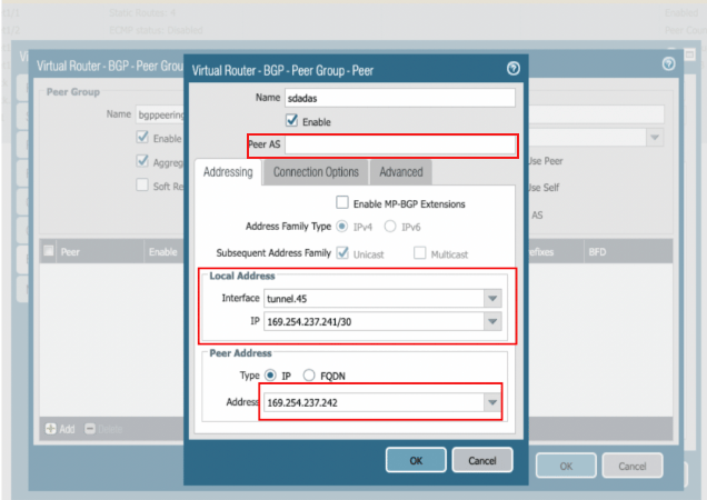
 g. After
everything is created, click OK to commit the configuration. The Router ID
is taken from the downloaded config file (it should be the IP address of the
tunnel created).
g. After
everything is created, click OK to commit the configuration. The Router ID
is taken from the downloaded config file (it should be the IP address of the
tunnel created).
 h. Click OK.
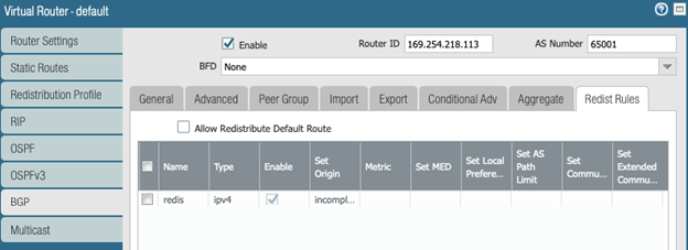
i. Navigate to Network > default > Redistribution Profile. j. On the IPv4
tab, click Add. k. In the Name field, enter ‘redis’. l. Enter a
priority. m. Select the connect Source Type to create a redistribution
profile.
h. Click OK.
i. Navigate to Network > default > Redistribution Profile. j. On the IPv4
tab, click Add. k. In the Name field, enter ‘redis’. l. Enter a
priority. m. Select the connect Source Type to create a redistribution
profile.
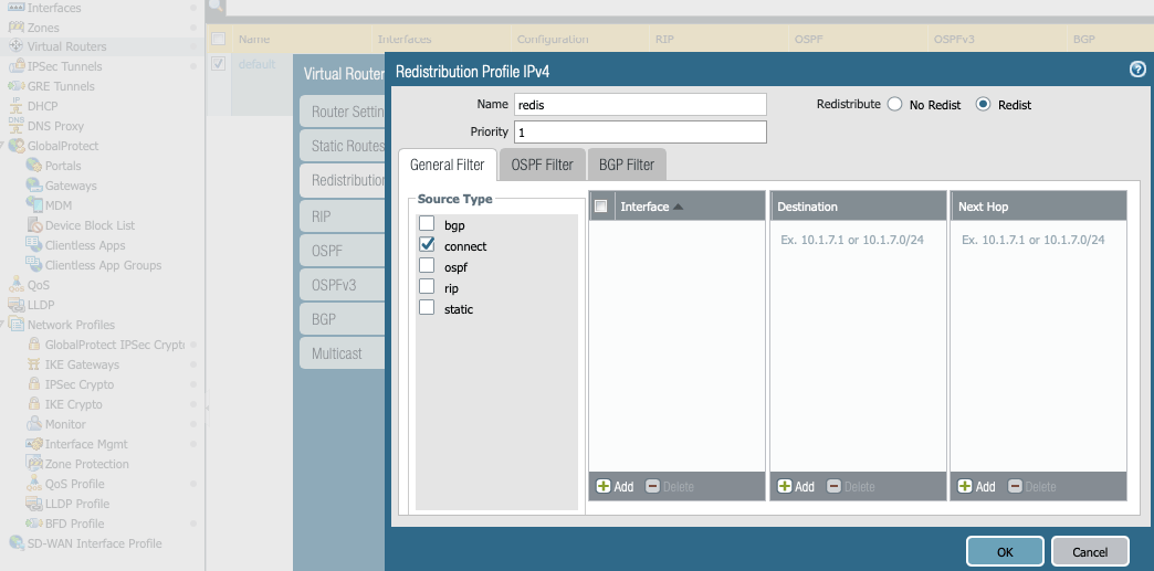
- In the AWS portal, configure the VPC Route Table associated with the private subnet of VPC2. Add a route with VPC1 private subnet as the destination and Palo Alto Networks VM LAN port as the gateway.
- In CoPilot, go to Diagnostics > Diagnostic Tools > BGP Diagnostics.
- Select the gateway name from the dropdown list.
- In the Command field, enter the ‘show Ip bgp’ command.
- Click Run to verify the BGP Routes.