

Scenario 1: On-prem Overlaps with Spoke in Aviatrix Transit Deployment
In this scenario, the Aviatrix Transit solution is deployed, and a resource on the on-prem site overlaps with a Spoke CIDR it needs to communicate with, as shown in the diagram below.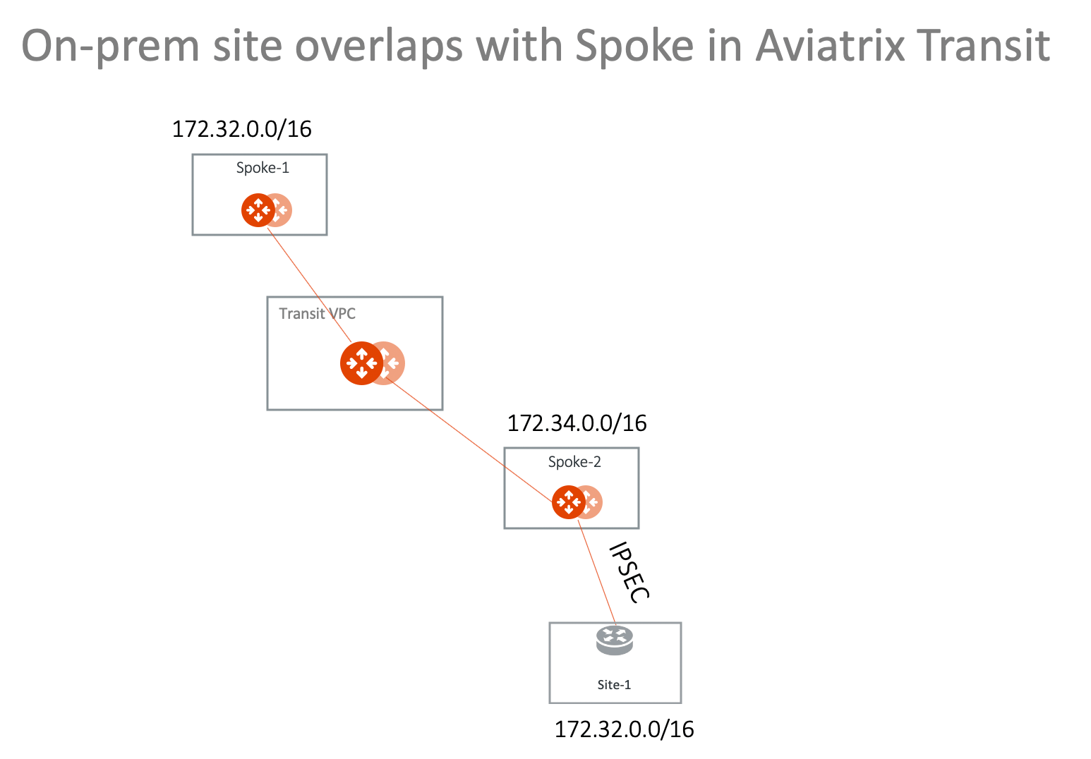
Scenario 2: Multi-Sites Overlap in Aviatrix Transit Deployment
This scenario extends the previous solution to include multi-sites, as shown in the diagram below.Scenario 3: On-prem Overlaps with Spoke VPC/VNet in TGW Deployment
In this scenario, on-prem site-1 overlaps with Spoke-1 VPC/VNet CIDR. They are both 172.32.0.0/16 and want to communicate with each other. The solution is to deploy an Aviatrix Gateway in Spoke-2 VPC/VNet and build an IPsec tunnel between Spoke-2 gateway and the on-prem. In the deployment, both Spoke-1 and Spoke-2 are attached to TGW and are in the same Network Domain. The diagram shown below illustrates how to use Spoke VPC Advertised Routes to build a more complex network. You can launch an Aviatrix Gateway in Spoke-1 directly and build the IPsec tunnel.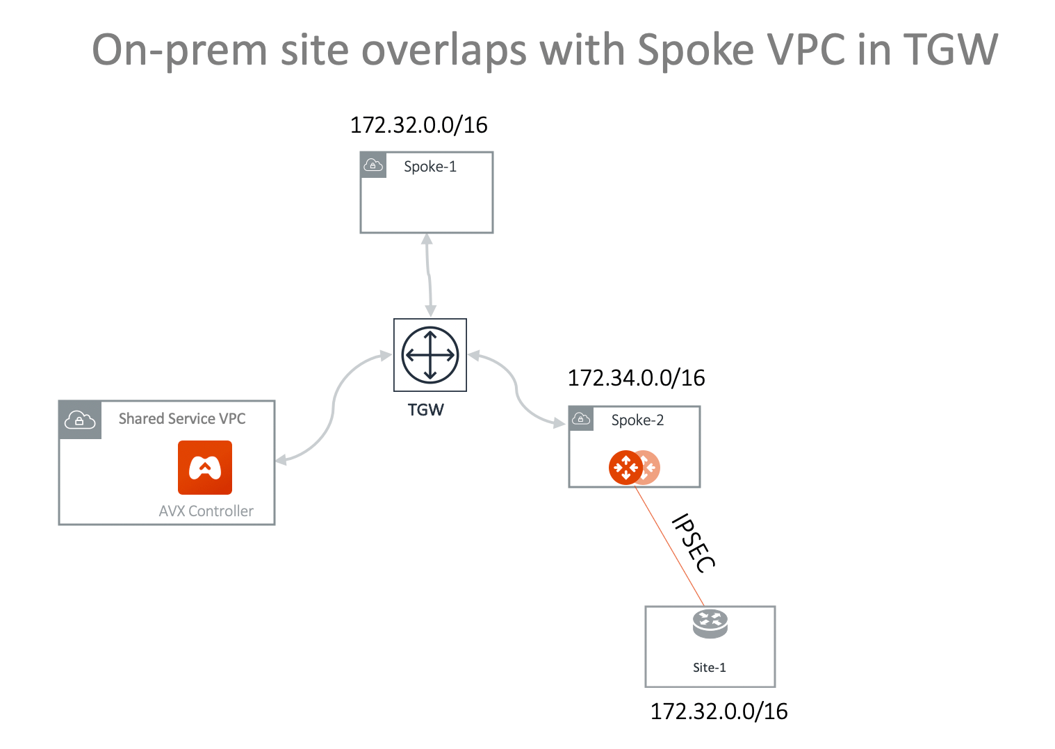
- Attach VPC/VNet Spoke-2 to TGW .
- Launch Aviatrix gateway in Spoke-2 . You can add an instance when creating the Spoke Gateway if you want to use HA.
- Create a Static Route-Based (Mapped) connection from Spoke-2 to Site-1 using these values:
-
Configure the on-premises site-1 IPsec. Key parameters are:
- Local Subnet: 172.32.0.0/16
- Remote Subnet: 192.168.0.0/16
- Check the tunnel status at Diagnostics > Cloud Routes > External Connections.
-
Advertise 100.100.0.0/16 to TGW from Spoke-2 VPC/VNet:
- On the Networking > Connectivity > AWS TGW tab, click the name of your AWS TGW.
- Click the Attachments sub-tab and then click VPC.
- Attach the Spoke VPC you created in Step 2 above and ensure that the Customize Spoke VPC Routes field contains 172.34.0.0/100, 100.100.0.0/16 (where 172.34.0.0/16 is the Spoke-2 VPC/VNet CIDR and 100.100.0.0/16 is the virtual network CIDR of on-prem site-1).
- Test connectivity. From on-prem site-1 to ping an instance in Spoke-1 using the Spoke-1 virtual network CIDR with the real host portion of its IP address. For example, if the instance in Spoke-1 is 172.32.10.15, then site-1 should ping 192.168.10.15.
Scenario 4: Multi-Sites Overlap in TGW Deployment
Scenario 1 can be extended to on-prem multi sites that have overlapping or identical network addresses, as shown in the diagram below.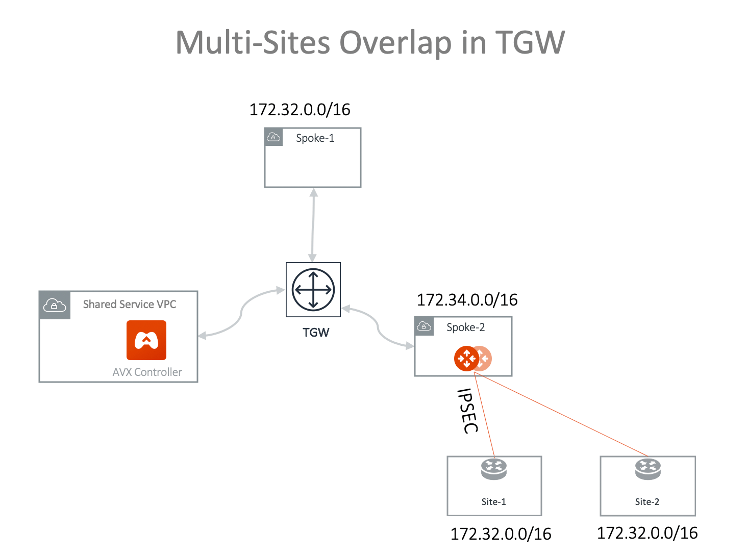
- Attach VPC/VNet Spoke-2 to TGW .
- Launch Aviatrix gateway in Spoke-2 . You can add an instance when creating the Spoke Gateway if you want to use HA.
- Create a Static Route-Based (Mapped) connection from Spoke2 to Site-1 using these values:
-
Create an on-premises site-1 to Spoke-2 Gateway IPsec connection with an
on-premises router or firewall:
- Route Based VPN
- Local Subnet: 172.32.0.0/16
- Remote Subnet: 192.168.0.0/16
- Check the tunnel status at Diagnostics > Cloud Routes > External Connections.
- Create a Static Route-Based (Mapped) connection from Spoke-2 to Site-2 using these values:
-
Create an on-prem site-2 to Spoke-2 gateway IPsec connection with an on-prem
router or firewall. Key parameters:
- Route Based VPN
- Local Subnet: 172.32.0.0/16
- Remote Subnet: 192.168.0.0/16
-
Advertise 100.100.0.0/16 100.200.0.0/16 to TGW from Spoke-2 VPC/VNet:
- On the Networking > Connectivity > AWS TGW tab, click the name of your AWS TGW.
- Click the Attachments sub-tab and then click VPC.
- Attach the Spoke-2 VPC if it is not attached already.
- Ensure that the Customize Spoke VPC Routes field contains 172.34.0.0/100, 100.100.0.0/16, 100.200.0.0/16 (where 172.34.0.0/16 is Spoke-2 VPC/VNet CIDR; 100.100.0.0/16 is the virtual network CIDR of on-prem site-1; and 100.200.0.0/16 is the virtual network CIDR of on-prem site-2).
- Test connectivity for on-prem site-1 by pinging an instance in Spoke-1 using the Spoke-1 virtual network CIDR with the real host portion of its IP address. For example, if the instance in Spoke-1 is 172.32.10.15, then site-1 should ping 192.168.10.15.
- Test connectivity for on-prem site-2 by pinging an instance in Spoke-1 using the Spoke-1 virtual network CIDR with the real host portion of its IP address. For example, if the instance in Spoke-1 is 172.32.10.15, then site-2 should ping 192.168.10.15.