> ## Documentation Index
> Fetch the complete documentation index at: https://docs.aviatrix.com/llms.txt
> Use this file to discover all available pages before exploring further.
# Example Configuration for FortiGate VM in AWS
> In this document, we provide an example to set up the FortiGate Next Generation Firewall instance for you to validate that packets are sent to the FortiGate Next Generation Firewall for VPC-to-VPC and from VPC-to-Internet traffic inspection.
In this document, we provide an example to set up the FortiGate Next Generation
Firewall instance for you to validate that packets are sent to the FortiGate
Next Generation Firewall for VPC-to-VPC and from VPC-to-Internet traffic
inspection.
You must first [create a Transit FireNet in AWS](https://legacy.docs.aviatrix.com/documentation/latest/security/transit-firenet-create-aws.html), and deploy a Fortinet FortiGate firewall in that Transit FireNet.
If you do not use Aviatrix vendor integration, you can manually configure
Fortinet route table entries. For AWS that does not use the AWS Native Load
Balancer, the RFC 1918 routes should point to the Aviatrix FireNet Gateway LAN
interface IP.
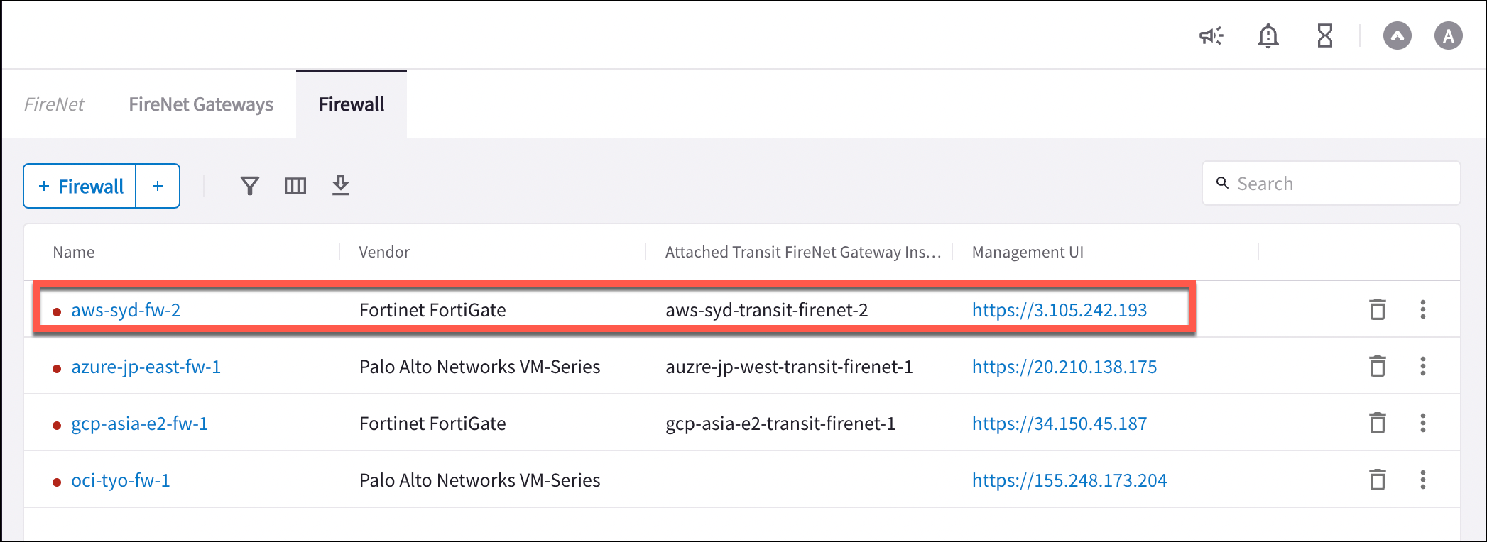
After you launch a FortiGate Next Generation Firewall instance, the FireNet >
Firewall tab displays the public IP address of the firewall's management/egress
interface. You click this to access the firewall UI.
 Here is the Firewall information in this example for your reference. Adjust it
depending on your requirements.
| **Example setting** | **Example value** |
| ------------------------ | ----------------------------------------------------------- |
| Firewall Image | Fortinet FortiGate Next-Generation Firewall |
| Firewall Image Version | 6.2.3 |
| Firewall Instance Size | c5.xlarge |
| Egress Interface Subnet | Select the subnet whose name contains "FW-ingress-egress." |
| Key Pair Name (Optional) | The .pem file name for SSH access to the firewall instance. |
| Attach | Check |
The FortiGate Next Generation Firewall instance has two interfaces as
described below. Additionally, firewall instance eth1 is on the same subnet as
FireNet gateway eth2 interface.
| **Fortigate VM instance interfaces** | **Description** | **Inbound Security Group Rule** |
| ----------------------------------------------- | ----------------------------- | ------------------------------- |
| eth0 (on subnet -Public-FW-ingress-egress-AZ-a) | Egress or Untrusted interface | Allow ALL |
| eth1 (on subnet -dmz-firewall) | LAN or Trusted interface | Allow ALL (Do not change) |
Below are the steps for initial setup.
## Vendor Integration (Optional)
Click
[here](https://legacy.docs.aviatrix.com/documentation/latest/security/fortigate-vendor-integration.html)
for information on vendor integration.
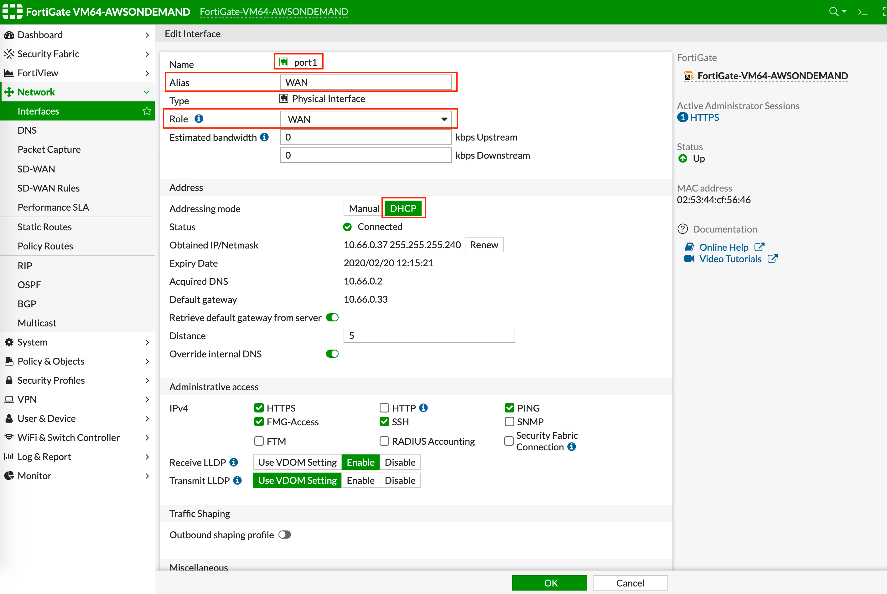
## Configuring FortiGate Next Generation Firewall port1 with WAN
After logging in with the new password, go to the page Network > Interfaces to
configure Physical Interface port1 as per the following screenshot.
Select the interface with port 1 and click **Edit**.
Enter an Alias (i.e.: WAN) for the interface.
Specify appropriate role (WAN).
Enable DHCP to ensure FW retrieve private IP information from the AWS console.
Enable **Retrieve default gateway from server**.
Here is the Firewall information in this example for your reference. Adjust it
depending on your requirements.
| **Example setting** | **Example value** |
| ------------------------ | ----------------------------------------------------------- |
| Firewall Image | Fortinet FortiGate Next-Generation Firewall |
| Firewall Image Version | 6.2.3 |
| Firewall Instance Size | c5.xlarge |
| Egress Interface Subnet | Select the subnet whose name contains "FW-ingress-egress." |
| Key Pair Name (Optional) | The .pem file name for SSH access to the firewall instance. |
| Attach | Check |
The FortiGate Next Generation Firewall instance has two interfaces as
described below. Additionally, firewall instance eth1 is on the same subnet as
FireNet gateway eth2 interface.
| **Fortigate VM instance interfaces** | **Description** | **Inbound Security Group Rule** |
| ----------------------------------------------- | ----------------------------- | ------------------------------- |
| eth0 (on subnet -Public-FW-ingress-egress-AZ-a) | Egress or Untrusted interface | Allow ALL |
| eth1 (on subnet -dmz-firewall) | LAN or Trusted interface | Allow ALL (Do not change) |
Below are the steps for initial setup.
## Vendor Integration (Optional)
Click
[here](https://legacy.docs.aviatrix.com/documentation/latest/security/fortigate-vendor-integration.html)
for information on vendor integration.
## Configuring FortiGate Next Generation Firewall port1 with WAN
After logging in with the new password, go to the page Network > Interfaces to
configure Physical Interface port1 as per the following screenshot.
Select the interface with port 1 and click **Edit**.
Enter an Alias (i.e.: WAN) for the interface.
Specify appropriate role (WAN).
Enable DHCP to ensure FW retrieve private IP information from the AWS console.
Enable **Retrieve default gateway from server**.
 ## Configuring FortiGate Next Generation Firewall port2 with LAN
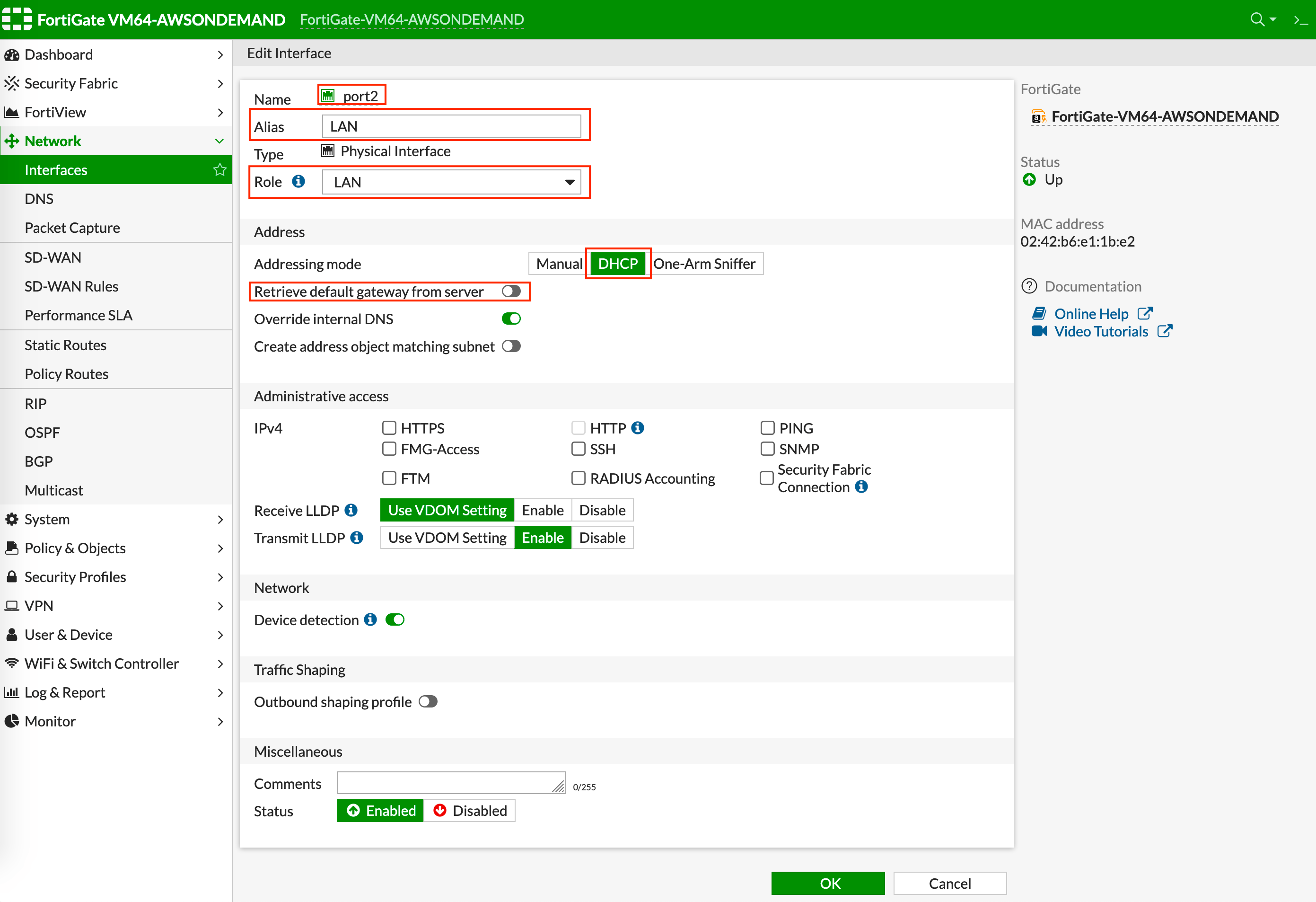
Go to the page Network > Interfaces to configure Physical Interface port2 as per
the following screenshot.
Select the interface with port 2 and click **Edit**.
Enter an Alias (i.e.: LAN) for the interface.
Specify appropriate role (LAN).
Enable DHCP to ensure FW retrieve private IP information from AWS console.
Enable Administrative Access: IPv4 > HTTPS.
Disable **Retrieve default gateway from server**.
## Configuring FortiGate Next Generation Firewall port2 with LAN
Go to the page Network > Interfaces to configure Physical Interface port2 as per
the following screenshot.
Select the interface with port 2 and click **Edit**.
Enter an Alias (i.e.: LAN) for the interface.
Specify appropriate role (LAN).
Enable DHCP to ensure FW retrieve private IP information from AWS console.
Enable Administrative Access: IPv4 > HTTPS.
Disable **Retrieve default gateway from server**.
 ## Creating Static Routes for Routing of Traffic VPC to VPC
Packets to and from TGW VPCs, as well as on-premises, will be hairpinned off the
LAN interface. As such, you need to configure appropriate route ranges that you
expect traffic for packets that need to be forward back to TGW. For simplicity,
you can configure the FW to send all RFC 1918 packets to LAN port, which sends
the packets back to the TGW.
In this example, we configure all traffic for RFC 1918 to be sent out of the LAN
interface.
In the FortiGate UI, go to Network > Static Routes to create a Static Route as
the following screenshot.
## Creating Static Routes for Routing of Traffic VPC to VPC
Packets to and from TGW VPCs, as well as on-premises, will be hairpinned off the
LAN interface. As such, you need to configure appropriate route ranges that you
expect traffic for packets that need to be forward back to TGW. For simplicity,
you can configure the FW to send all RFC 1918 packets to LAN port, which sends
the packets back to the TGW.
In this example, we configure all traffic for RFC 1918 to be sent out of the LAN
interface.
In the FortiGate UI, go to Network > Static Routes to create a Static Route as
the following screenshot.
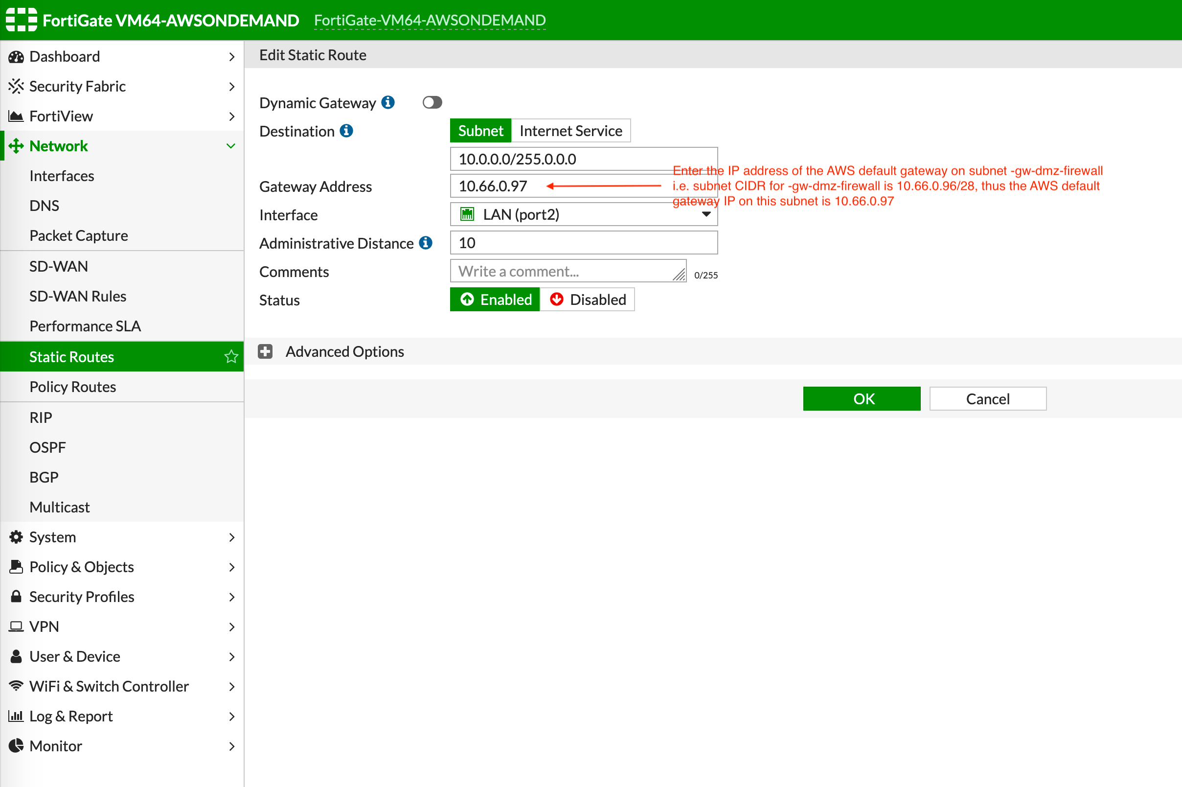 Click **Create New**.
Enter the destination route in **Destination**.
In **Gateway Address**, you will need to enter the AWS default gateway IP on
subnet -dmz-firewall.
The subnet CIDR for -dmz-firewall is 10.66.0.96/28, thus the AWS default
gateway IP on this subnet is 10.66.0.97.
The interface will be the LAN (port2).
Configure an appropriate admin distance if you expect overlapping routes that
need to be prioritized.
Enter comments as necessary.
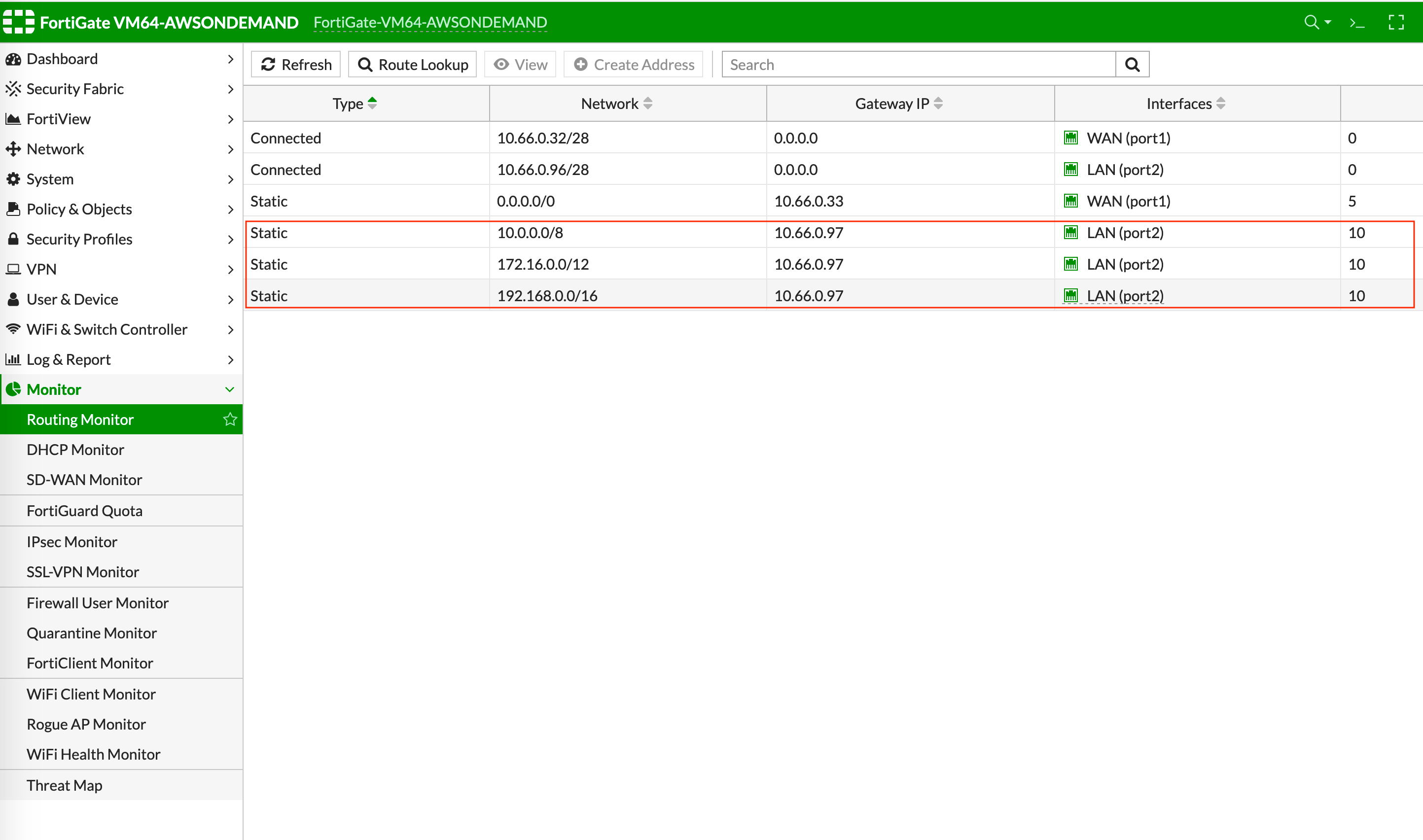
Repeat the steps above for RFC 1918 routes.
Those static routes can also be reviewed by navigating to Monitor > Routing
Monitor.
Click **Create New**.
Enter the destination route in **Destination**.
In **Gateway Address**, you will need to enter the AWS default gateway IP on
subnet -dmz-firewall.
The subnet CIDR for -dmz-firewall is 10.66.0.96/28, thus the AWS default
gateway IP on this subnet is 10.66.0.97.
The interface will be the LAN (port2).
Configure an appropriate admin distance if you expect overlapping routes that
need to be prioritized.
Enter comments as necessary.
Repeat the steps above for RFC 1918 routes.
Those static routes can also be reviewed by navigating to Monitor > Routing
Monitor.
 ## Configuring Basic Traffic Policy to Allow Traffic VPC-to-VPC
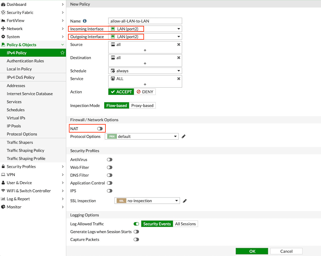
In this step, you will configure a basic traffic security policy that allows
traffic to pass through the firewall. Given that Aviatrix Gateways will only
forward traffic from the TGW to the LAN port of the Firewall, you can set your
policy condition to match any packet that is going in/out of the LAN interface.
In the Fortigate UI, navigate to Policy & Objects > IPv4 Policy > Create New /
Edit to configure the policy as shown in the following table.
| Field | Value |
| ------------------ | ---------------------------------- |
| Name | Configure any name for this policy |
| Incoming Interface | LAN (port2) |
| Outgoing Interface | LAN (port2) |
| Source | Click on the + sign and add all |
| Destination | Click on the + sign and add all |
| Schedule | always |
| Service | ALL |
| Action | ACCEPT |
| NAT | Disabled |
## Configuring Basic Traffic Policy to Allow Traffic VPC-to-VPC
In this step, you will configure a basic traffic security policy that allows
traffic to pass through the firewall. Given that Aviatrix Gateways will only
forward traffic from the TGW to the LAN port of the Firewall, you can set your
policy condition to match any packet that is going in/out of the LAN interface.
In the Fortigate UI, navigate to Policy & Objects > IPv4 Policy > Create New /
Edit to configure the policy as shown in the following table.
| Field | Value |
| ------------------ | ---------------------------------- |
| Name | Configure any name for this policy |
| Incoming Interface | LAN (port2) |
| Outgoing Interface | LAN (port2) |
| Source | Click on the + sign and add all |
| Destination | Click on the + sign and add all |
| Schedule | always |
| Service | ALL |
| Action | ACCEPT |
| NAT | Disabled |
 After validating that your TGW traffic is being routed through your firewall
instances, you can customize the security policy to your requirements.
## (Optional) Configuring Basic Traffic Policy to Allow Traffic from a VPC to the Internet
In this step, we will configure a basic traffic security policy that allows
Internet traffic to pass through the firewall. Given that Aviatrix Gateways will
only forward traffic from the TGW to the LAN port of the Firewall, you can set
your policy condition to match any packet that is going into the LAN interface
and going out of the WAN interface.
First you enable egress inspection:
In CoPilot, select FireNet on the left.
On the FireNet Gateways tab, select a Transit FireNet in the list and click the
pencil (Edit) icon.
In the Edit FireNet dialog, under FireNet Configuration, toggle the Egress
slider to **On**.
On the FireNet tab, verify the Egress status by making sure that the Egress
column reads yes.
You then create the new traffic policy in the FortiGate UI:
Navigate to Policy & Objects > IPv4 Policy > Create New / Edit to configure the
policy as per the following table.
| Field | Value |
| ------------------ | ---------------------------------- |
| Name | Configure any name for this policy |
| Incoming Interface | LAN (port2) |
| Outgoing Interface | WAN (port1) |
| Source | Click on the + sign and add all |
| Destination | Click on the + sign and add all |
| Schedule | always |
| Service | ALL |
| Action | ACCEPT |
| NAT | Enable |
After validating that your TGW traffic is being routed through your firewall
instances, you can customize the security policy to your requirements.
## (Optional) Configuring Basic Traffic Policy to Allow Traffic from a VPC to the Internet
In this step, we will configure a basic traffic security policy that allows
Internet traffic to pass through the firewall. Given that Aviatrix Gateways will
only forward traffic from the TGW to the LAN port of the Firewall, you can set
your policy condition to match any packet that is going into the LAN interface
and going out of the WAN interface.
First you enable egress inspection:
In CoPilot, select FireNet on the left.
On the FireNet Gateways tab, select a Transit FireNet in the list and click the
pencil (Edit) icon.
In the Edit FireNet dialog, under FireNet Configuration, toggle the Egress
slider to **On**.
On the FireNet tab, verify the Egress status by making sure that the Egress
column reads yes.
You then create the new traffic policy in the FortiGate UI:
Navigate to Policy & Objects > IPv4 Policy > Create New / Edit to configure the
policy as per the following table.
| Field | Value |
| ------------------ | ---------------------------------- |
| Name | Configure any name for this policy |
| Incoming Interface | LAN (port2) |
| Outgoing Interface | WAN (port1) |
| Source | Click on the + sign and add all |
| Destination | Click on the + sign and add all |
| Schedule | always |
| Service | ALL |
| Action | ACCEPT |
| NAT | Enable |
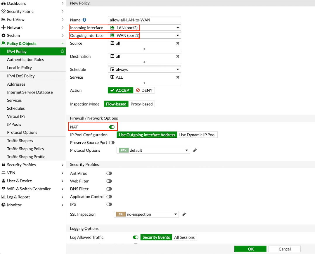 The NAT function needs to be enabled on this VPC to Internet policy.
After validating that your TGW traffic is being routed through your firewall
instances, you can customize the security policy to your requirements.
## Packet Inspection and Attaching VPC to AWS TGW
Now your firewall instance is ready to receive packets.
The next step is to specify which Network Domain needs packet inspection by
defining a
[connection policy](https://legacy.docs.aviatrix.com/documentation/latest/security/transit-firenet-inspection-policy.html)
that connects to the Firewall Domain. In addition, attach VPC to TGW by
Step 1
in the TGW Orchestrator Build workflow.
For example, deploy Spoke-1 VPC in Network\_Domain\_1 and Spoke-2 VPC in
Network\_Domain\_2. Build a connection policy between the two domains. Build a
connection between Network\_Domain\_2 to Firewall Domain.
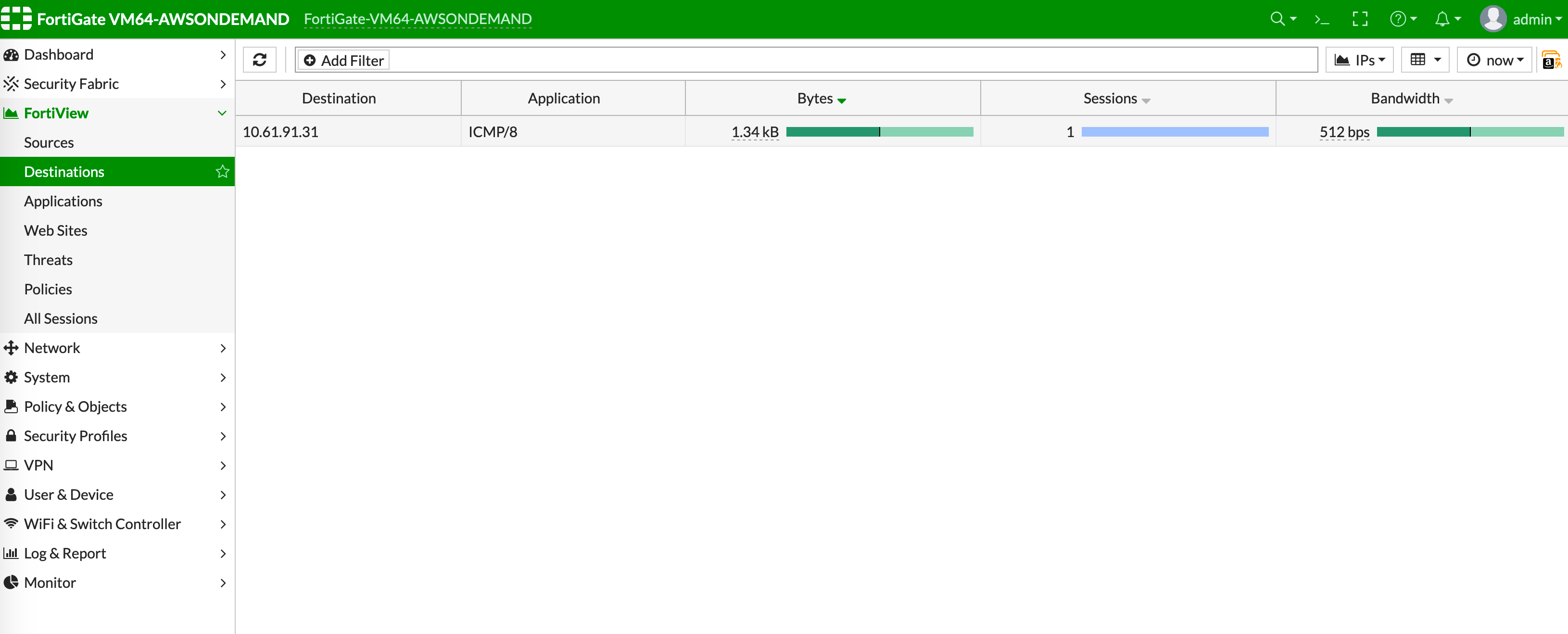
## Viewing the Traffic Log
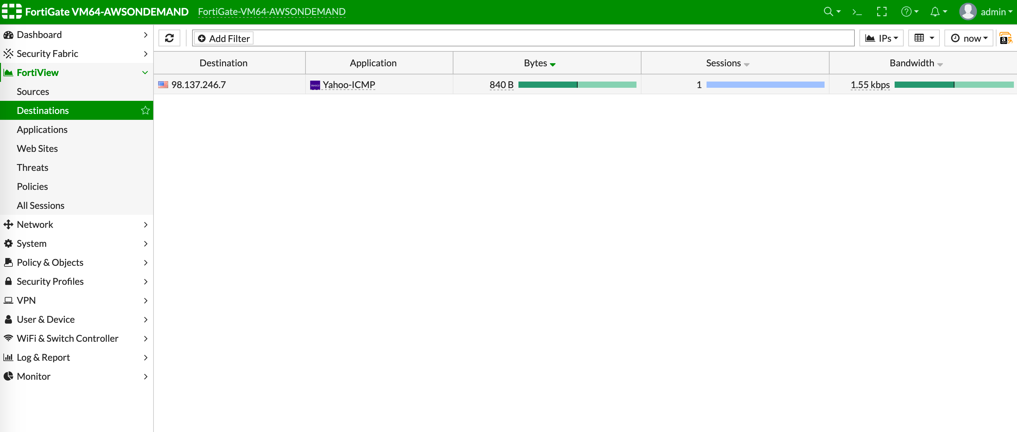
You can view if traffic is forwarded to the firewall instance by logging in to
the FortiGate Next Generation Firewall console. Go to FortiView > Destinations.
## VPC-to-VPC Traffic
Launch one instance in Spoke-1 VPC and one in Spoke-2 VPC. Start pinging packets
from an instance in Spoke-1 VPC to the private IP of another instance in Spoke-2
VPC where one or both of the Network Domains are connected to Firewall Network
Domain. The ICMP traffic should go through and be inspected on the firewall.
The NAT function needs to be enabled on this VPC to Internet policy.
After validating that your TGW traffic is being routed through your firewall
instances, you can customize the security policy to your requirements.
## Packet Inspection and Attaching VPC to AWS TGW
Now your firewall instance is ready to receive packets.
The next step is to specify which Network Domain needs packet inspection by
defining a
[connection policy](https://legacy.docs.aviatrix.com/documentation/latest/security/transit-firenet-inspection-policy.html)
that connects to the Firewall Domain. In addition, attach VPC to TGW by
Step 1
in the TGW Orchestrator Build workflow.
For example, deploy Spoke-1 VPC in Network\_Domain\_1 and Spoke-2 VPC in
Network\_Domain\_2. Build a connection policy between the two domains. Build a
connection between Network\_Domain\_2 to Firewall Domain.
## Viewing the Traffic Log
You can view if traffic is forwarded to the firewall instance by logging in to
the FortiGate Next Generation Firewall console. Go to FortiView > Destinations.
## VPC-to-VPC Traffic
Launch one instance in Spoke-1 VPC and one in Spoke-2 VPC. Start pinging packets
from an instance in Spoke-1 VPC to the private IP of another instance in Spoke-2
VPC where one or both of the Network Domains are connected to Firewall Network
Domain. The ICMP traffic should go through and be inspected on the firewall.
 ## \[Optional] VPC to Internet Traffic
Launch a private instance in the Spoke VPC (i.e. Spoke-2 VPC) where the Network
Domain (i.e. Network\_Domain\_2) is connected to Firewall Network Domain. Start
pinging packets from the private instance to the Internet service to verify
egress function. The ICMP traffic should go through and be inspected on the
firewall.
## \[Optional] VPC to Internet Traffic
Launch a private instance in the Spoke VPC (i.e. Spoke-2 VPC) where the Network
Domain (i.e. Network\_Domain\_2) is connected to Firewall Network Domain. Start
pinging packets from the private instance to the Internet service to verify
egress function. The ICMP traffic should go through and be inspected on the
firewall.